UPS Electrical Installation
9
5. For control connection details, see 2.4 - Control Cable and Communication.
6. Close and secure the interior and exterior doors.
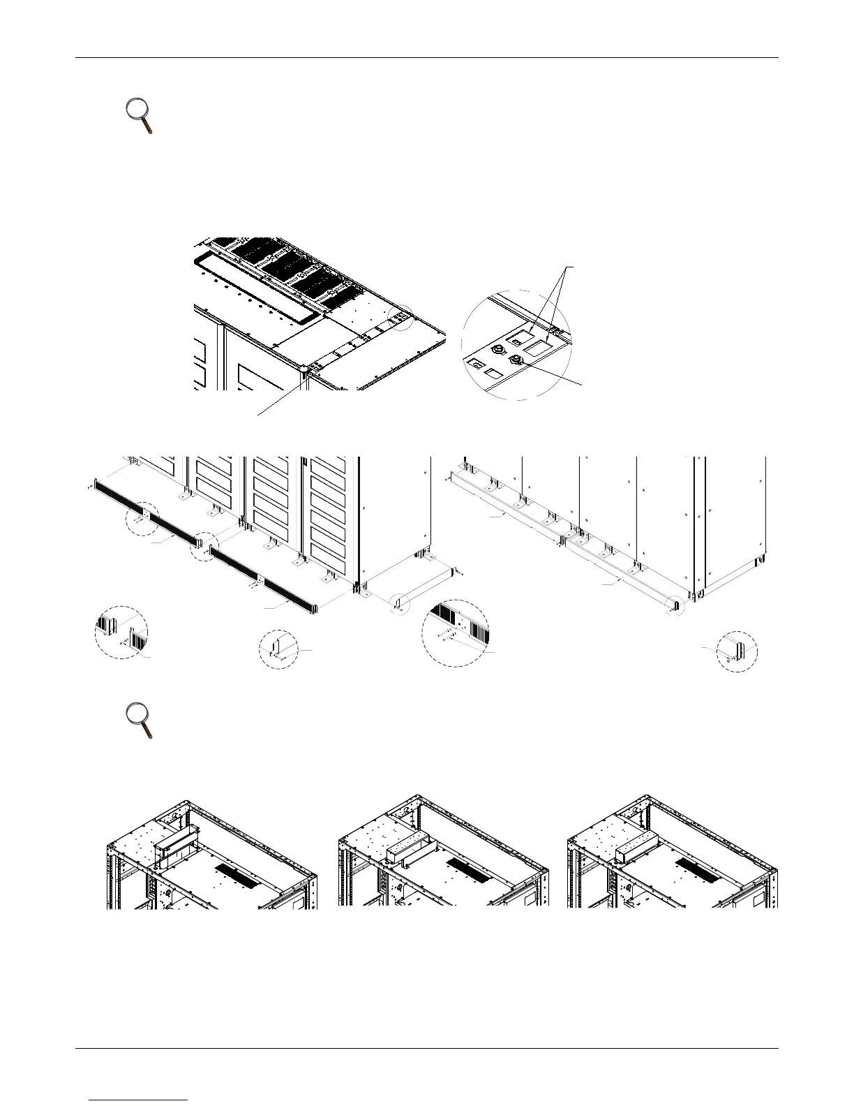
7. 500kVA-750kVA Only—Attach the cabinet grounding plates to the top of the UPS at each
shipping split. See Figure 2.
8. Attach the kick plates and filters to the bottom of the unit. See Figure 3.
Figure 2 Cabinet grounding plates
Figure 3 Kick plate and filter locations
Figure 4 Low-voltage cable installation—top entry
NOTE
If fault bracing brackets were removed during installation, they MUST be replaced.
NOTE
Kick plates must be installed. If the unit is to be installed in a position that does not permit
access to rear kick plates, then the kick plates must be installed before the unit is placed in its
final position.
Note location
of larger cutouts.
Orient ground plate
as shown.
A
Mounting
Hardware
(Supplied)
Installed at Each Shipping Split
Detail A
Install Factory-Supplied
Bolt, Lockwasher and
Washer, 4 Places,
Front Side
Install Factory-Supplied
Bolt, Lockwasher and
Washer, 4 Places,
Rear Side
Install Factory-Supplied
Bolt, Lockwasher and
Washer, 2 Places
Each Side
Install Factory-Supplied
Bolt, Lockwasher and
Washer, 2 Places,
Each Side
FRONT
Kickplate
Kickplate
REAR
Kickplate
Kickplate
Kickplate
D
DETAIL D
E
DETAIL E
G
DETAIL G
F
Low-voltage cables can be install through the top of each unit. The entry conduit landing plate is shipped inverted.
To install, remove conduit plate, flip and reinstall. Removal of side plate is for access to pull wires.
REMOVE PLATES
FLIP PLATES
INSTALL
 Loading...


