UPS Electrical Installation
14
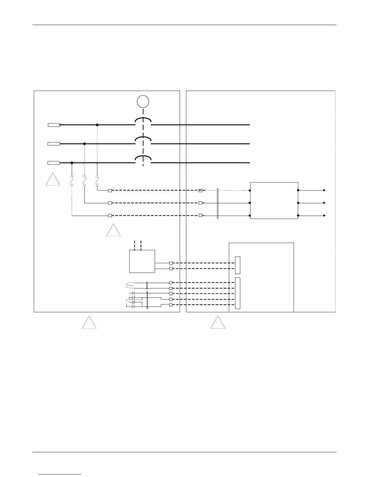
2.4.3 Remote Input Breaker (RIB)
For systems that use Remote Input Breakers (RIB), the controls for the Aux contacts, UVR, Motor
Operator (optional) and voltage sense will go between the Remote breaker and the UPS Input I/O
section. See Figure 7.
Figure 7 Remote Input Breaker diagram
A
B
C
E
RIB
10A 10A 10A
IN_LINE_A
IN_LINE_B
IN_LINE_C
INPUT EMI
FILTER
IN_LOAD_A
IN_LOAD_B
IN_LOAD_C
A
B
C
A
B
C
LINE LOAD
V_IN_R_A
V_IN_R_B
V_IN_R_C
4 CB1_ COIL _RTN
3_CB1_NO (CB CLOSED)
2_CB1_NC (CB OPEN)
5 CB1_ COIL
1_CB1_COM
Inside UPS Cabinet
RIB
UVR Coil
(48VDC)
RIB Status
Contacts
120-240VAC
Close
RIB
RCB1
Electrical
Oper ator
120-240VAC
(supplied by
swichgear vendor)
5_ M TR_ OP_ CLOSE
2_MTR_OP_ENABLE
Circuit Breaker
Interface Board
02-806711-01
Inside Switchgear
To Customer
Input
Terminals
1
2
1
2
12
RIB-1
1
1
Fuses should be 10A class CC or J type time delay
fuse
2
Electrical operator power provided by switchgear
vendor and shall be powered from line side of RIB
TB1
TB1-1
TB1-2
TB1-3
2
TB1101
TB1102
 Loading...


