UPS Electrical Installation
20
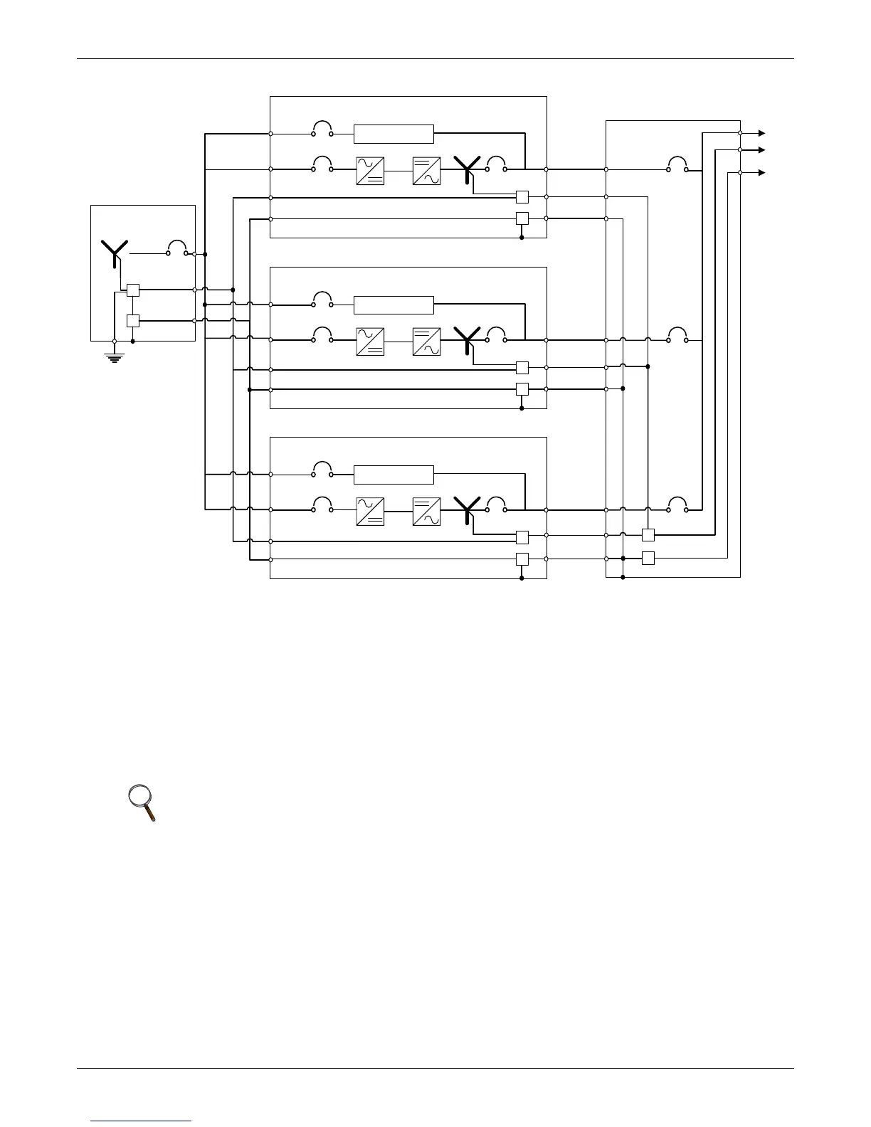
Figure 11 Grounding diagram—Four-wire multi-module systems
2.6.2 Three-Wire Input connections
This configuration must NOT be used when single-phase loads are directly connected to the UPS. The
UPS output is considered a separately derived source. The UPS module neutral is bonded to the UPS
ground and connected to a local grounding electrode in accordance with the NEC. Please note that
whenever the UPS module transfers to or from bypass, two AC sources (UPS output and bypass) are
briefly connected together and circulating current must flow. In this configuration, the current flows
through the ground path, possibly tripping ground fault interrupters (GFIs) and distorting the output
voltage waveform. Proper adjustment of ground fault interrupters is necessary to avoid unwanted
tripping. The time delay should be set to at least 0.2 seconds to prevent tripping when the UPS
performs a transfer or retransfer operation.
CAUTION
Failure to set the ground fault interrupters properly could cause loss of power to the critical
load.
Switchgear
UPS #1
Source
G
N
BPSS
N
G
UPS #2
BPSS
N
G
UPS #3
BPSS
N
G
To connect equipment
N
G
 Loading...


