Installation Drawings
58
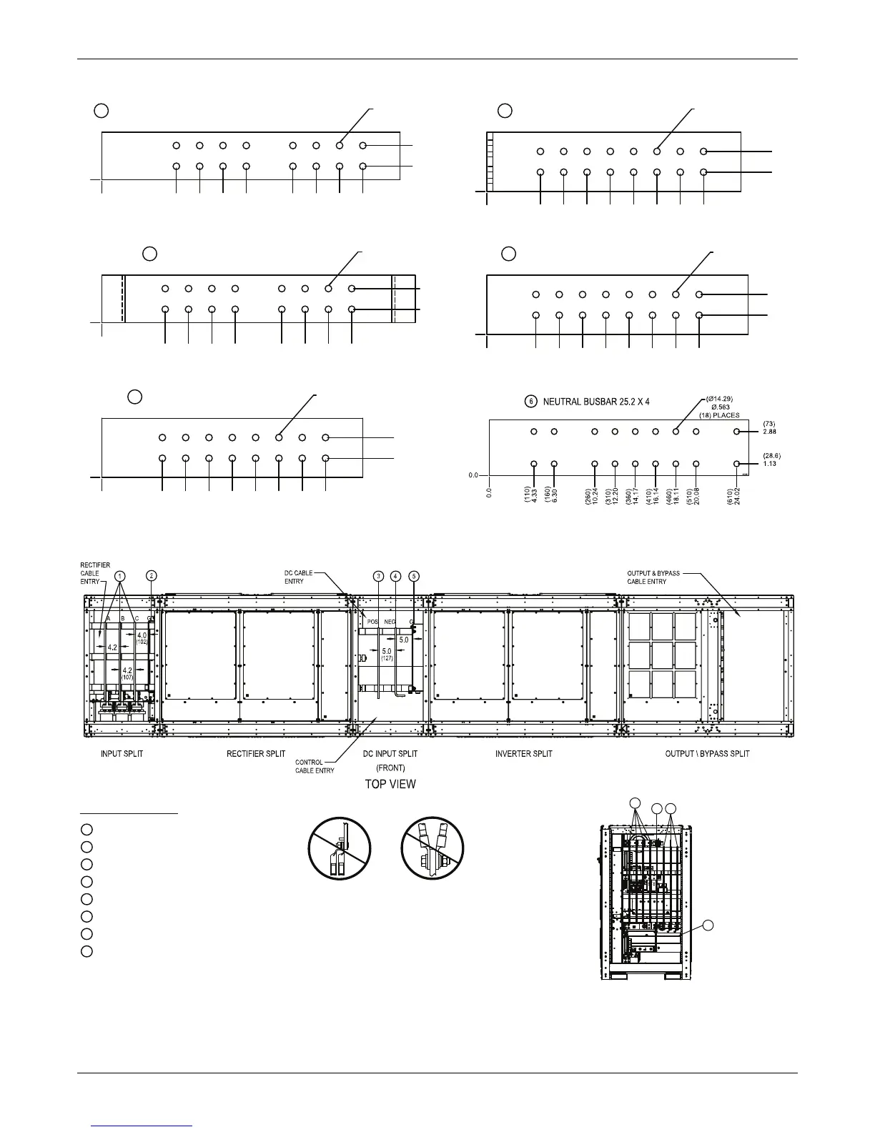
Figure 45 Busbar terminal details, 1100kVA UPS, N+1 multi-module without static bypass
Figure 46 Terminal details, 1100kVA UPS, 1+N multi-module or SMS with static bypass
(28.6)
1.13
(73)
2.88
0.0
(160)
6.30
(210)
8.27
(260)
10.24
(310)
12.20
(410)
16.14
(460)
18.11
(510)
20.08
(560)
22.05
(14.29)
.563
(16) PLACES
1
INPUT/OUTPUT PHASE BUSBAR 25.2 X 4
0.0
(136.2)
5.36
(186.2)
7.33
(236.2)
9.30
(286.2)
11.27
(386.2)
15.20
(436.2)
17.17
(486.2)
19.14
(536.2)
21.11
2
GROUND BUSBAR 26.5 X 4
(14.29)
.563
(16) PLACES
0.0
0.0
(28.6)
1.13
(73)
2.88
(14.29)
.563
(16) PLACES
(130)
5.12
(180)
7.09
(230)
9.06
(280)
11.02
(330)
12.99
(380)
14.96
(430)
16.93
(480)
18.90
3
DC POS. BUSBAR 22.1 X 5
(14.29)
.563
(16) PLACES
(41.3)
1.63
(85.7)
3.38
(14.29)
.563
(16) PLACES
0.0
0.0
(115)
4.53
(165)
6.50
(215)
8.46
(265)
10.43
(315)
12.40
(365)
14.37
(415)
16.34
(465)
18.31
4
DC NEG. BUSBAR 21.46 X 5
(14.29)
.563
(16) PLACES
(14.29)
.563
(16) PLACES
0.0
0.0
(105.4)
4.15
(155.4)
6.12
(205.4)
8.09
(255.4)
10.06)
(305.4)
12.02
(355.4)
13.99
(405.4)
15.96
(455.4)
17.93
5
DC GROUND BUSBAR 22.1 X 5
0.0
0.0
(14.29)
.563
(16) PLACES
(14.29)
.563
(16) PLACES
(41.3)
1.63
(85.7)
3.38
(41.3)
1.63
(85.7)
3.38
543894
543880
543931
543930
543932
Notes:
1. All dimensions are in inches (mm).
2. Control wiring and power wiring must be run in separate conduits.
3. Aluminum and copper-clad aluminum cables are not recommended.
4. All wiring is to be in accordance with national and local electrical codes.
1
Input phase busbar
2
Ground busbar
3
DC pos. busbar
4
DC neg. busbar
5
DC ground busbar
6
SEE BUSBAR DETAIL FIGURE ( U40-11E-3200B-NFC-00)
7
Bypass input, neutral, & output busbar
8
Neutral output busbar
Ground bypass busbar
RIGHT SIDE VIEW
6
BFB C,B,A,
& NEU. BYP.
7
6
CB2 C,B,A OUTPUT
8
3.5 (89) SPACING
BETWEEN BUSBARS
DO NOT DOUBLE STACK THE LUGS. THIS IS TO PREVENT THE
CABLES FROM COMING INTO CONTACT WITH OTHER BUSBARS.
CB1-3
CB1-3
 Loading...


