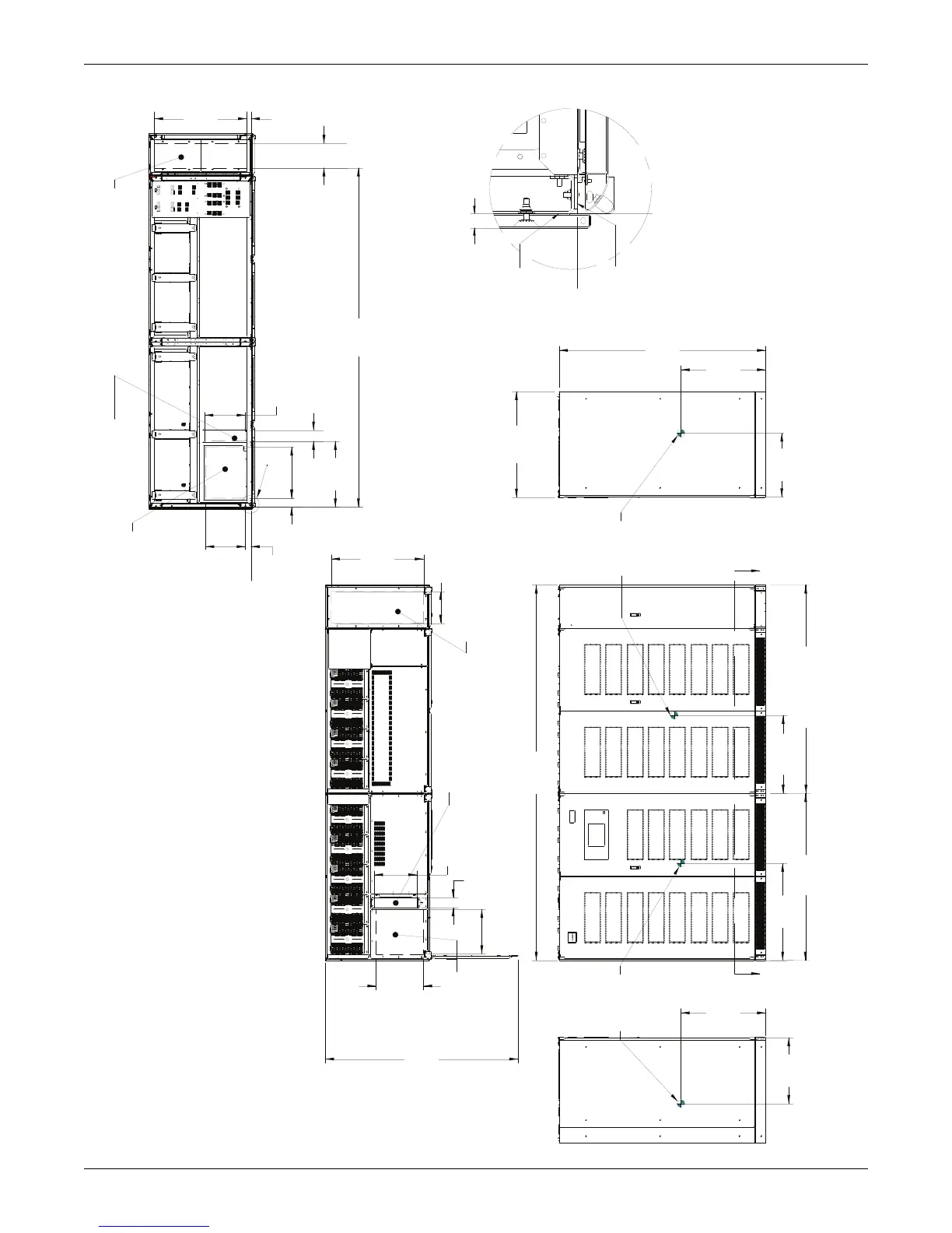
NOTES
1. All dimensions are in inches (mm).
2. 24" (610) minimum clearance above unit required for air exhaust and maintenance..
3. Keep cabinet within 15 degrees of vertical.
4. Top and bottom cable entry available through removable access plates.
Remove, punch to suit conduit size and replace.
5. Unit bottom is structurally adequate for forklift handling.
6. Depth dimension includes front door and rear panel.
7. Width dimensions include side panels. subtract 1.4" (35mm) when removing both side panels.
RECTIFIER
CENTER OF
62.5
[1587]
78.0
[1981]
INVERTER SPLIT (PART B)
24.6
[625]
31.5
[800]
36.3
[922]
29.1
[739]
A
GRAVITY
140.5
[3568]
LEFT SIDE VIEW FRONT VIEW
RECTIFIER SPLIT (PART A)
A
INVERTER
76.8
[1950]
34.1
[866]
23.8
[605]
CENTER OF
GRAVITY
39.4
[1000]
RIGHT SIDE VIEW
OUTER EDGE
CORNER POST
FRONT MOST
EDGE OF FRAME
.0
(0)
.0
(0)
.6
[15]
PANEL WIDTH
DETAIL B
RECTIFIER / DC
CABLE ENTRY
CONTROL CABLE
ENTRY \ EXIT
71.6
[1819]
15.8
[402]
3.7
[94]
17.6
[447]
TOP VIEW
16.6
[423]
11.9
[302]
34.3
[871]
BYPASS \ OUTPUT
CABLE EXIT
RECTIFIER / DC
CABLE ENTRY
CONTROL CABLE
ENTRY / EXIT
.0
(0)
.0
(0)
3.3
[85]
14.8
[376]
2.1
[53]
19.1
[486]
24.6
[626]
15.2
[385]
4.1
[105]
SECTION A-A
BOTTOM VIEW
B
9.2
[233]
34.3
[872]
BYPASS \ OUTPUT
CABLE EXIT.
126.8
[3220]
1.6
[40]
 Loading...


