Installation Drawings
57
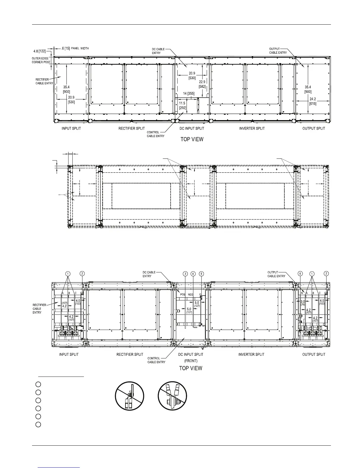
Figure 43 Conduit landing drawing 1100kVA UPS N+1 multi-module without static bypass
Figure 44 Terminal details 1100kVA UPS, N+1 multi-module without static bypass
NOTE
1. All dimensions are in inches (mm).
BOTTOM VIEW
(TOP LOOKING DOWN)
RECTIFIER SPLITINPUT SPLIT INVERTER SPLIT
OUTPUT SPLIT
DC INPUT SPLIT
17.9
(455)
21.1
(536)
17.9
(455)
21.1
(536)
17.9
(455)
21.1
(536)
(FRONT)
1.6
(40)
OUTER EDGE
CORNER POST
3.1
(80)
OUTER EDGE
CORNER POST
RECTIFIER
CABLE ENTRY
TYP.
DC CABLE
ENTRY TYP.
OUTPUT CABLE
ENTRY TYP.
DO NOT DOUBLE-STACK THE LUGS. THIS IS TO PREVENT THE
CABLES FROM COMING INTO CONTACT WITH OTHER BUSBARS.
CB1-3
CB1-3
Notes:
1. All dimensions are in inches (mm).
2. Control wiring and power wiring must be run in separate conduits.
3. Aluminum and copper-clad aluminum cables are not recommended.
4. All wiring is to be in accordance with national and local electrical codes.
1
Input/output phase busbar
2
Ground busbar
3
DC pos. busbar
4
DC neg. busbar
5
DC ground busbar
6
Neutral busbar
SEE BUSBAR DETAIL U40-11E-3000B-NFC-00
 Loading...


