Installation Drawings
39
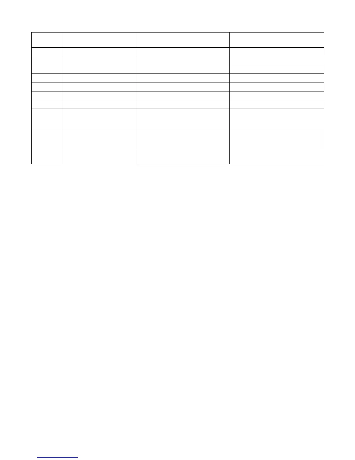
WH P/N
START
(Part A - Rectifier Cabinet)
FINISH
(Part B - Inverter Cabinet) LABEL
531985G1 UPSC (Control Door) 02-806704-Inverter Gate Drive A To: 02-806704- Phase A ID: P0400A
531988G2 UPSC (Control Door) 02-806707-Load Vi To: 02-806707-ID: P0700
531983G1 UPSC (Control Door) 02-806707-Load Vi To: 02-806707- ID: P0701
531985G2 UPSC (Control Door) 02-806704-inverter Gate Drive B To: 02-806704- Phase B ID: P0400B
531985G3 UPSC (Control Door) 02-806704-Inverter Gate Drive C To: 02-806704- Phase C ID: P0400C
531984G1 UPSC (Control Door) 02-806705-Bypass Control Board To: 02-806705-ID: P0500
531988G1 UPSC (Control Door) 02-806705-Bypass Control Board To: 02-806705-ID: P0501
532061G1 Power Supply 02-806716-AC Distribution Board
To: 02-806716-__
Connection ID: P1305
WH P/N: 532061G1
532062G1 Power Supply 02-806705- Bypass Control Board
To: 02-806705-__
Connection ID: P44
WH P/N: 532062G1
532062G1 Power Supply F42-2 & F43-2 Bypass PS Fuse Block
To: F42-2 and F43-2
WH P/N: 532062G1
 Loading...


