Cerabar S/Deltabar S Level measurement (ToF Tool)
Endress+Hauser 85
9 Select LEVEL MIN parameter.
P01-xxxxxxxx-05-xx-xx-xx-017
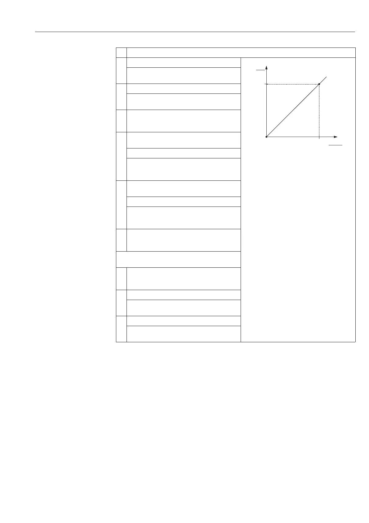
Fig. 14: Calibrating the 1st measured variable
1 See table, step 9.
2 See table, step 10.
3 See table, step 12.
4 See table, step 13.
Enter the minimum level to be expected, here 0 m for
example.
10 Select LEVEL MAX parameter.
Enter the maximum level to be expected, here 3 m for
example. See also the following note, point 3.
11 Select the "Wet" option via the CALIBRATION MODE
parameter (calibration mode for the 1st measured
variable).
12 The pressure for the lower calibration point is present at
the device, here 0 mbar for example.
Select EMPTY CALIB. parameter.
Enter the level value, here 0 m for example. Confirm the
value to assign the pressure value present to the lower
level value.
13 The pressure for the upper calibration point is present at
the device, here 300 mbar for example.
Select FULL CALIB. parameter.
Enter the level value, here 3 m for example. Confirm the
value to assign the pressure value present to the upper
level value.
14 Result:
The calibration for the 1st measured variable is carried
out.
Perform linearisation (calibration for the 2nd
measured variable)
15 Change the function group.
Menu path: OPERATING MENU → SETTINGS →
LINEARISATION
16 Select TANK CONTENT MIN parameter.
Specify the minimum tank contents to be expected, here
0 m
3
for example.
17 Select TANK CONTENT MAX parameter.
Specify the maximum tank contents to be expected, here
5 m
3
for example.
Description
p
[mbar]
➂➀
➁➃
3
0
h
[m]
0 300