Cerabar S/Deltabar S Flow measurement (ToF Tool)
Endress+Hauser 91
9.2 Totalizers
Example:
In this example, the volume flow should be totalised and displayed in the unit m
3
E
3
. Negative flows
should be added to the flow rate.
!
Note!
• For a description of the parameters mentioned, see
– Page 134 ff, ToF Tool, table 15: TOTALIZER SETUP
– Page 144 ff, ToF Tool, table 23: PROCESS VALUES
• Totalizer 1 can be reset. Totalizer 2 cannot be reset.
!
Note!
• You can also specify a customer-specific unit. → See parameter description for TOTALIZER 1
UNIT (→ Page 134) and TOTALIZER 2 UNIT (→ Page 135).
• The TOTALIZER 1 and TOTAL. 1 OVERFLOW parameters display the totalised flow value of the
first totalizer. The TOTALIZER 2 and TOTAL. 2 OVERFLOW parameters display the totalised
flow value of the second totalizer. → See Page 144 ff, PROCESS VALUES function group.
• You can use the MENU DESCRIPTOR parameter (→ Page 136) to specify which measured value
should be displayed on the on-site display.
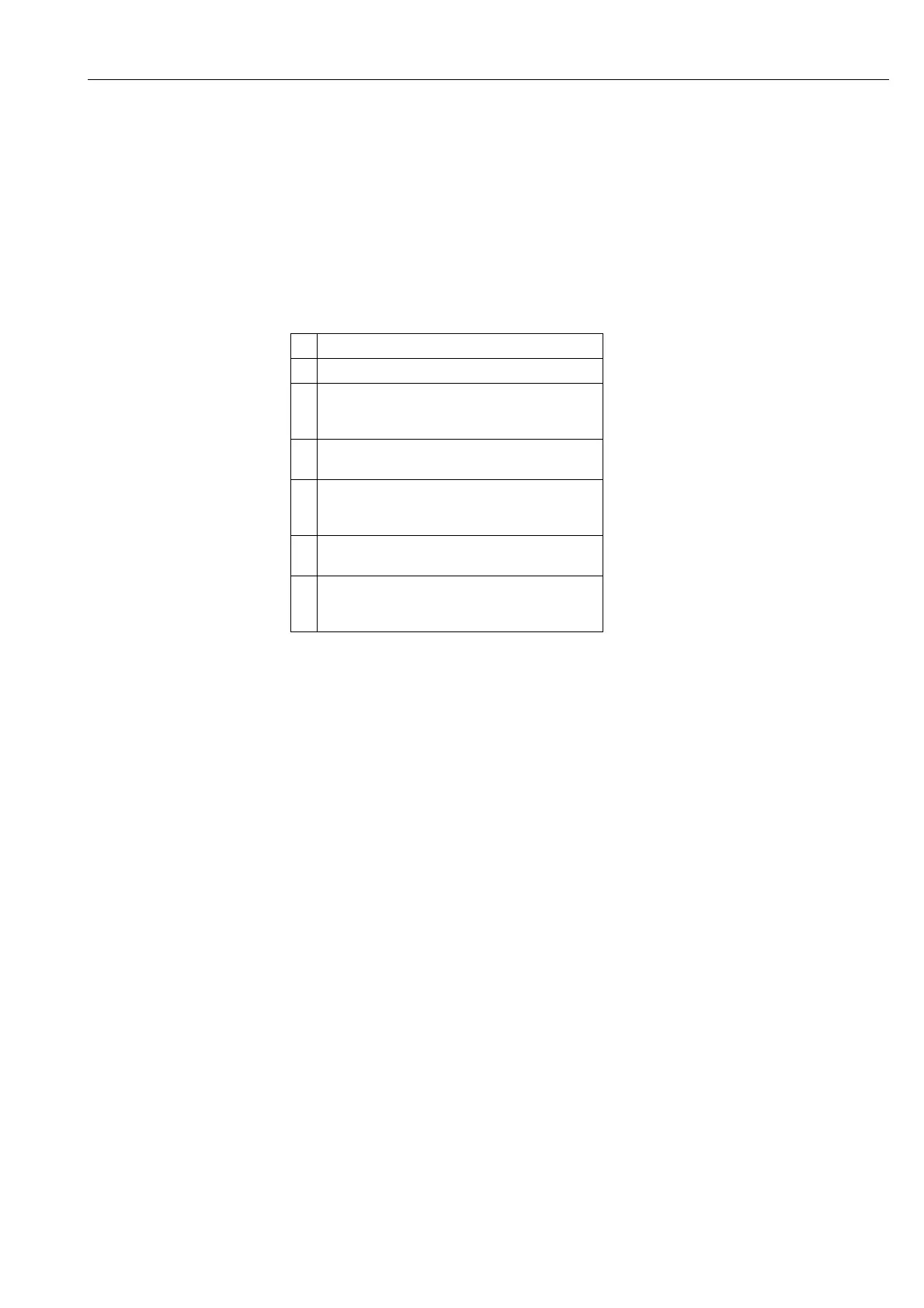
Description
1 Calibrate the device as per Section 5.1.
2 Change the function group:
OPERATING MENU → SETTINGS → TOTALIZER
SETUP
3 Select a flow unit via the TOTALIZER 1 UNIT
parameter, here m
3
E
3
for example.
4 Use the NEG. FLOW TOT. 1 parameter to specify the
totalising mode for negative flows, here the "Positive"
option for example.
5 Reset totalizer 1 to zero via the RESET TOTALIZER
parameter.
6Result:
The TOTALIZER 1 and TOTAL. 1 OVERFLOW
parameters display the totalised volume flow.