Cerabar S/Deltabar S Trouble-shooting
Endress+Hauser 159
11.2 Response of outputs to errors
The device differentiates between the message types "Alarm", "Warning" and "Error".
→ See the following table and Page 151, Section 11.1 "Messages".
11.2.1 Defining "Error"-type messages by means of the "Select
Alarmtype" method
For "Error"-type messages, you can specify whether the device should react as in the event of an
alarm or as in the event of a warning. → For "Error"-type messages, please refer to Page 158, Table,
"Error type" column. You can use the "Select Alarmtype" method in the Diagnostic Transducer Block
for dialog-guided alarm-type selection.
1. A warning message is output if the Diagnostic Transducer Block is not in the OOS mode.
2. "Set block mode to OOS. To do so, enter "1" and confirm.
3. For "Error No. " enter the error number, e.g. 120 and confirm.
4. For the "Select Alarmtype" prompt, enter either "1" for alarm or "2" for warning and confirm.
5. The "Method completed successfully" message is displayed.
6. Select the desired block mode: "1" for Auto or "3" for OOS.
7. The "Select Alarmtype" method is completed with the "Method execution has completed"
message.
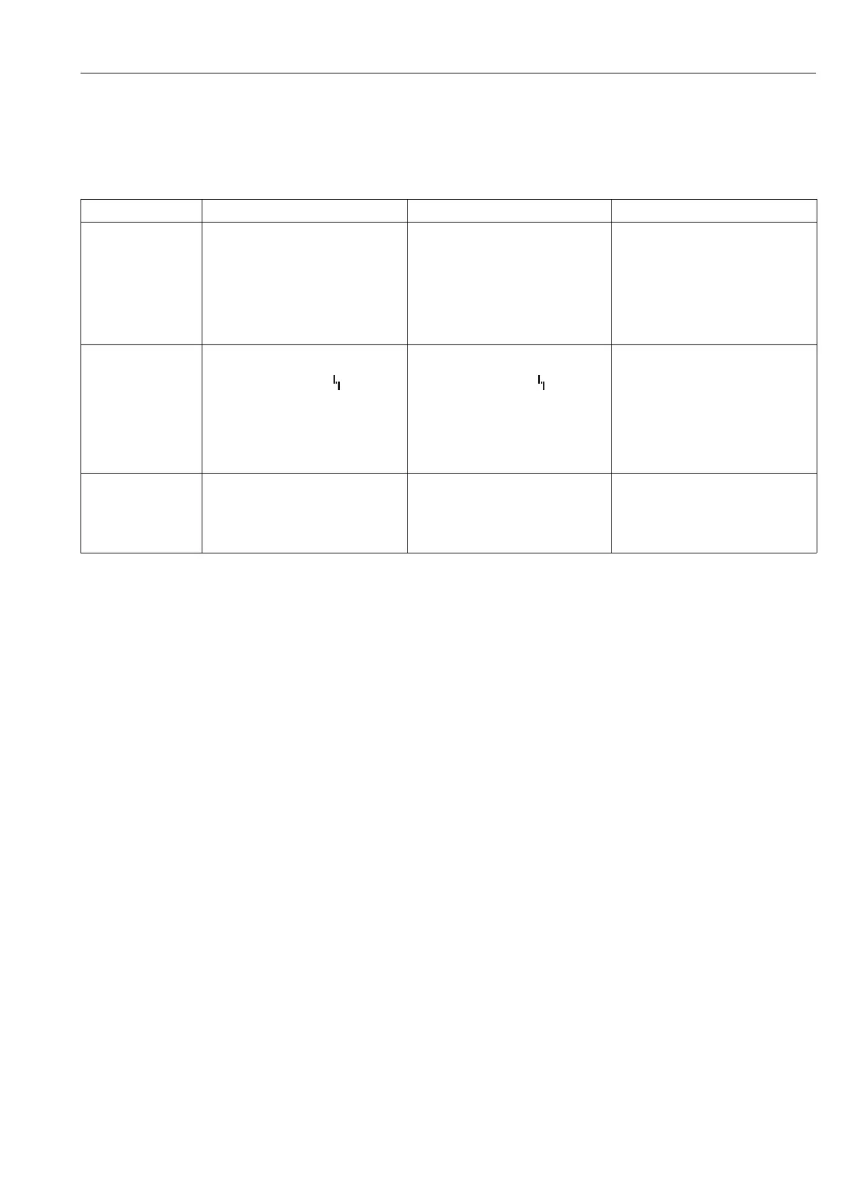
Output A (Alarm) W (Warning) E (Error: Alarm/Warning)
PFOUNDATION
Fieldbus
The process variable in question is
transmitted with the status BAD.
Device continues measuring. The process
variable in question is transmitted with the
status UNCERTAIN.
For this error, you can enter whether the
device should react as in the event of an
alarm or as in the event of a warning. See
corresponding "Alarm" or "Warning"
column.
(→ See also Page 62 or Page 149,
parameter description, REACTION_ON_
ALARM_NR/SELECT ALARM TYPE.)
On-site display – The measured value and message are
displayed alternately
– Measured value display: -symbol is
permanently displayed.
Message display
– A + 3-digit number such as A122 and
–Description
– The measured value and message are
displayed alternately
– Measured value display: -symbol
flashes.
Message display:
– W + 3-digit number such as W613 and
–Description
– The measured value and message are
displayed alternately
– Measured value display: see
corresponding "Alarm" or "Warning"
column
Message display:
– E + 3-digit number such as E713 and
–Description
Remote operation
(FF configuration
program/ToF Tool)
In the case of an alarm, the
DIAGNOSTIC_CODE/ALARM STATUS
parameter displays a
1
3-digit number such
as 122 for "Sensor connection error,
incorrect data."
In the case of a warning, the
DIAGNOSTIC_CODE/ALARM STATUS
2
parameter displays a 3-digit number such as
613 for "Simulation is active".
In the case of an error, the
DIAGNOSTIC_CODE/ALARM STATUS
parameter
2
displays a 3-digit number such
as 731 for "Pmax ALARM WINDOW
undershot".
1) FF configuration program: Diagnostic Transducer Block. Menu path ToF Tool: OPERATING MENU → MESSAGES