Wiring Gammapilot M FMG60 with FOUNDATION Fieldbus
22 Endress+Hauser
4 Wiring
4.1 Terminal compartments
4.2 Cable entries
!
Note!
• On delivery, not more than one cable gland is present for each of the terminal compartments. If
further cable glands are required (e.g. for cascading mode), they must be supplied by the user.
• Connecting cables should be routed away from the housing from below to prevent moisture from
penetrating the connection compartment. Otherwise, a drain loop should be provided or the
Gammapilot M should be fitted with a weather protection cover.
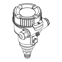
The Gammapilot M has got two terminal
compartments:
• terminal compartment A, for
–Power supply
– Signal output (depending on the device
version)
• terminal compartment B, for
– Signal output (depending on the device
version)
– PT-100 input (4-wire)
– Pulse input for cascading mode
– Pulse output for cascading mode
– Display and operating module FHX40
(or VU331)
!
Note!
Depending on the device version, the signal
output is located in the terminal compartment A
or B.
Maximum cable length:
• For cascade, 20 m each
• For PT-100 2 m (temperature should be
measured as close as possible to density
measurement)
L00-FMG60xxx-05-00-00-xx-041
A
B
The number and type of cable entries depend on
the device version ordered. The following types
may occur:
• Gland M20x1.5
tightening diameter (clamping range):
7.0 to 10.5 mm
• Cable entry M20x1.5
• Cable entry G1/2
• Cable entry NPT1/2
• M12 connector (see "Fieldbus connectors")
• 7/8" connector (see "Fieldbus connector")
In addition, Gammapilot M has a socket to
connect the separate display and operating unit
FHX 40. The housing of the Gammapilot M
does not have to be opened to connect the
FHX 40.
L00-FMG60xxx-04-00-00-xx-003
A: Cable entries for terminal compartment A;
B: Cable entries for terminal compartment B;
1: Socket for FHX 40
1
B
A

 Loading...


