Technical data Micropilot FMR60B PROFINET with Ethernet-APL
70 Endress+Hauser
15 Technical data
15.1 Input
Measured variable The measured variable is the distance between the reference point and the product
surface. The level is calculated based on "E", the empty distance entered.
Measuring range The measuring range starts at the point where the beam hits the tank floor. Levels below
this point cannot be measured, particularly in the case of spherical bases or conical outlets.
Maximum measuring range
The maximum measuring range depends on the antenna size and design.
Antenna Maximum measuring range
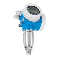
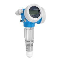
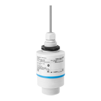
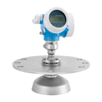
Encapsulated, PVDF, 40 mm (1.5 in) 40 m (131 ft)
Drip-off, PTFE, 50 mm (2 in) 50 m (164 ft)
Integrated, PEEK, 20 mm (0.75 in) 10 m (32.8 ft)
Integrated, PEEK, 40 mm (1.5 in) 22 m (72 ft)
Usable measuring range
The usable measuring range depends on the antenna size, the medium's reflective
properties, the installation position and any possible interference reflections.
In principle, measurement is possible up to the tip of the antenna.
To avoid any material damage from corrosive or aggressive media or deposit buildup on
the antenna, the end of the measuring range should be selected 10 mm (0.4 in) before the
tip of the antenna.

 Loading...
