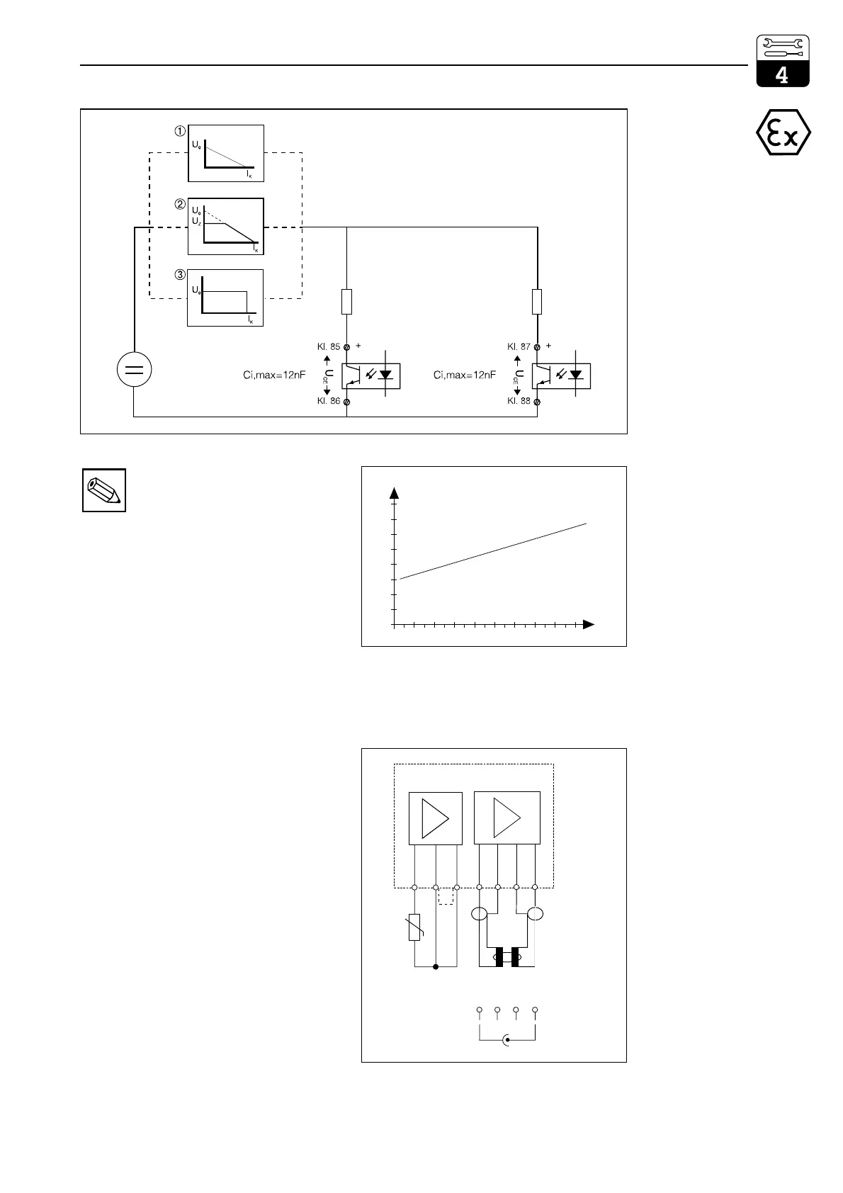
Note:
The optocoupler outputs are
high-impedance in case of a power
failure.
FCL1 additional module
11 Pt 100 terminal, sensor line
12 Pt 100 terminal, sensor line
13 Cable compensation terminal
For inductive sensor
14 Transmitter coil inner conductor
15 Transmitter coil screen
16 Receiver coil screen
17 Receiver coil inner conductor
For conductive sensor
14 Electrode cable screen
15 not connected
16 not connected
17 Electrode cable inner conductor
Connection data for power circuits,
terminals 11 to 17:
C
a,max
=50nF
L
a,max
=100µH
Measuring channel allocation
Cond.1 / temperature 1 Slot 1
Cond.2 / temperature 2 Slot 2
asx_fcga.eps
User 2
Basic module
Electrical data of contact circuit:
max. output voltage U
0
,max = 30 V
max. output power P
a
,max = 750 mW
User 1
Fig. 4.16
External wiring of output
contacts on basic module:
Only one intrinsically safe
contact circuit (ia or ib)
with
➀ linear
P
a
= ¼ (U
0
·I
K
)
➁ trapezoidal
1.) U
Z
> 0.5 U
0
P
a
= ¼ (U
0
·I
K
)
2.) U
Z
< 0.5 U
0
P
a
=(U
0
-U
Z
)·U
i
/R
i
➂ or square-wave
P
a
= (U
0
·I
K
)
output characteristic
0 10 203040 5060 708090[mA]
2.0
1.5
1.0
0.5
0
[v]
I
C
U
CE
IC_UCE_E.CDR
Fig. 4.17
Characteristic of
switching transistors on
basic module and FCYK
module (with output on)
11 12 13 14 15 16 17
Pt 100
fcl1.cdr
inductive
conductive
Only
two-electrode
sensors
connectable
14 15 16 17
n.c. n.c.
send (wt)
receive (rd)
Fig. 4.18
Connection of FCL1
module
lm152e04.chp
Mycom CLM 152 Installation
Endress+Hauser 19

 Loading...


