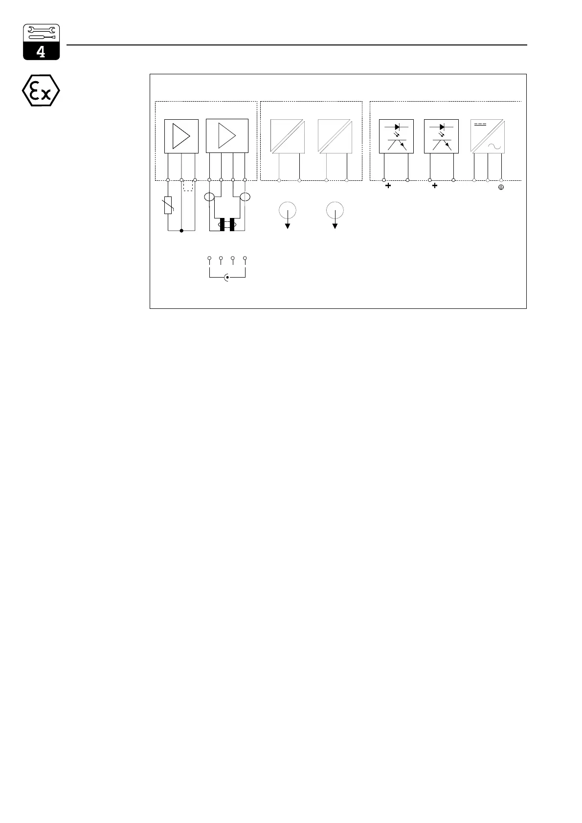
FCL1 module (slot 1, basic configuration):
11 Pt 100 terminal, sensor line
12 Pt 100 terminal, sensor line
13 Cable compensation terminal
For inductive sensor
14 Transmitter coil inner conductor
15 Transmitter coil screen
16 Receiver coil screen
17 Receiver coil inner conductor
For conductive sensor
14 Electrode cable screen
15 not connected
16 not connected
17 Electrode cable inner conductor
Connection data for power circuits,
terminals 11 to 17:
C
a,max
=50nF
L
a,max
= 100 µH
FCYI module (slot 2, basic configuration):
Active current output:
31 Current output (Cd signal) positive
32 Current output (Cd signal) negative
33 Current output (temp. signal) positive
34 Current output (temp. signal) negative
Connection data for power circuits,
terminals 31 to 34:
U
max
=16.4VI
max
=65mA
P
max
=1.1W
C
a,max
=40nF L
a,max
= 100 µH
Terminal blocks (basic configuration):
Power supply:
L AC voltage, phase
N AC voltage, neutral
PE Protective earth
Output contacts:
85 Alarm contact +
86 Alarm contact –
87 Contact 1 +
88 Contact 1 –
++
-
-
-
-
Conductivity input module (Ex) i
FCL1 (Slot 1)
Current output module (Ex) i
FCYI (Slot 2)
Basic module
Temperature Conductivity Conductivity Temperature Fail Contact 1 Aux. voltage
Pt 100
lm152cox.cdr
11 12 13 14 15 16 17 31 32 33 34 85 86 87 88 L N PE (AC)
bl rt rt bl
Con
mA
ϑ
mA
Conϑ
L+ L
- (DC)
receive (rd)
send (wt)
14 15 16 17
n.c. n.c.
Only
two-electrode
sensors
connectable
Fig. 4.15
Wiring diagram for
CLM 152-Z (base version)
inductive
conductive
Installation Mycom CLM 152
18 Endress+Hauser

 Loading...


