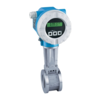
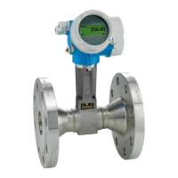
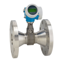
Wiring Proline Prowirl 73
30 Endress+Hauser
Connection diagram for reading in external temperature/pressure values via the
HART protocol
!
Note!
• For configuring and commissioning external temperature/pressure sensors, see ä 57
• The pulse/frequency output remains available in the following circuit diagrams and can be used
to output the mass flow or the temperature for example. The external temperature sensor for delta
heat measurements, e.g. Omnigrad TR10 with TMT182 head transmitter, is shown in gray.
• The minimum resistor power must be 1W.
PLC with common "plus"
A0001774
Fig. 19: Connection diagram for PLC with common "plus"
Dotted line = alternative wiring when only the signal of the Prowirl 73 is fed to the PLC.
A Prowirl 73
B Pressure sensor (Cerabar M, S HART with BURST OPTION = 1 and Burst-Mode = ON)
C Temperature sensor (Omnigrad TR10) or other external measuring devices (HART-enabled and burst-enabled)
D Active barrier RN221N
!
Note!
To be able to use the analog 4 to 20 mA device current output, e.g. for transmitting the measured
value to a PLC, set the HART address of the device to "0" (factory setting).
Every address not equal to "0" results in a constant current of 4 mA at the output
(COMMUNICATION, FIELDBUS ADDRESS ä 138).
250W
0+H
0–
1
2
I+ I–
0– 0+H0+0+
PLC+PLC (73) in
DD
I+
I–
1
2
1
2
C
A B
PLC (p/T) inPLC+

 Loading...


