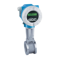
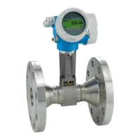
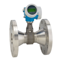
Proline Prowirl 73 Wiring
Endress+Hauser 29
Wiring diagram
A0001897
Fig. 17: Assignment of terminals
A Power supply/current output
B Optional frequency output can also be operated as:
– A pulse or status output
– A PFM output together with the RMC or RMS621 flow computer (see below)
C Ground terminal (only relevant for remote version)
Connecting the device to the RMC or RMS621 flow computer
The device can output PFM (pulse/frequency modulation) signals together with the RMC or
RMS621 flow computer.
!
Note!
To output vortex pulses directly, the VORTEX FREQUENCY option must be selected in the
OPERATION MODE function (ä 122).
A0001898
Fig. 18: Assignment of the terminals for connecting to the RMC or RMS621 flow computer
A Device
B RMC or RMS621 flow computer
a Terminal 83 (loop supply 2 +); terminal 110 (input 2 - mA/PFM/pulse), slot AII
b Terminal 82 (loop supply 1 +); terminal 10 (input 1 - mA/PFM/pulse), slot AI
c Ground terminal (only relevant for remote version)
12 34
a
c
A
B
++ + +
-- - -
b
10 11082 83

 Loading...


