EasyManua.ls Logo

ENSONIQ DP/4+ User Manual

ENSONIQ DP/4+
199 pages
To Next Page IconTo Next Page
To Previous Page IconTo Previous Page
Page #40 background imageLoading...
Page #40 background image
Section 1 — Controls & Basic Functions
24 ENSONIQ DP/4+ Reference Manual
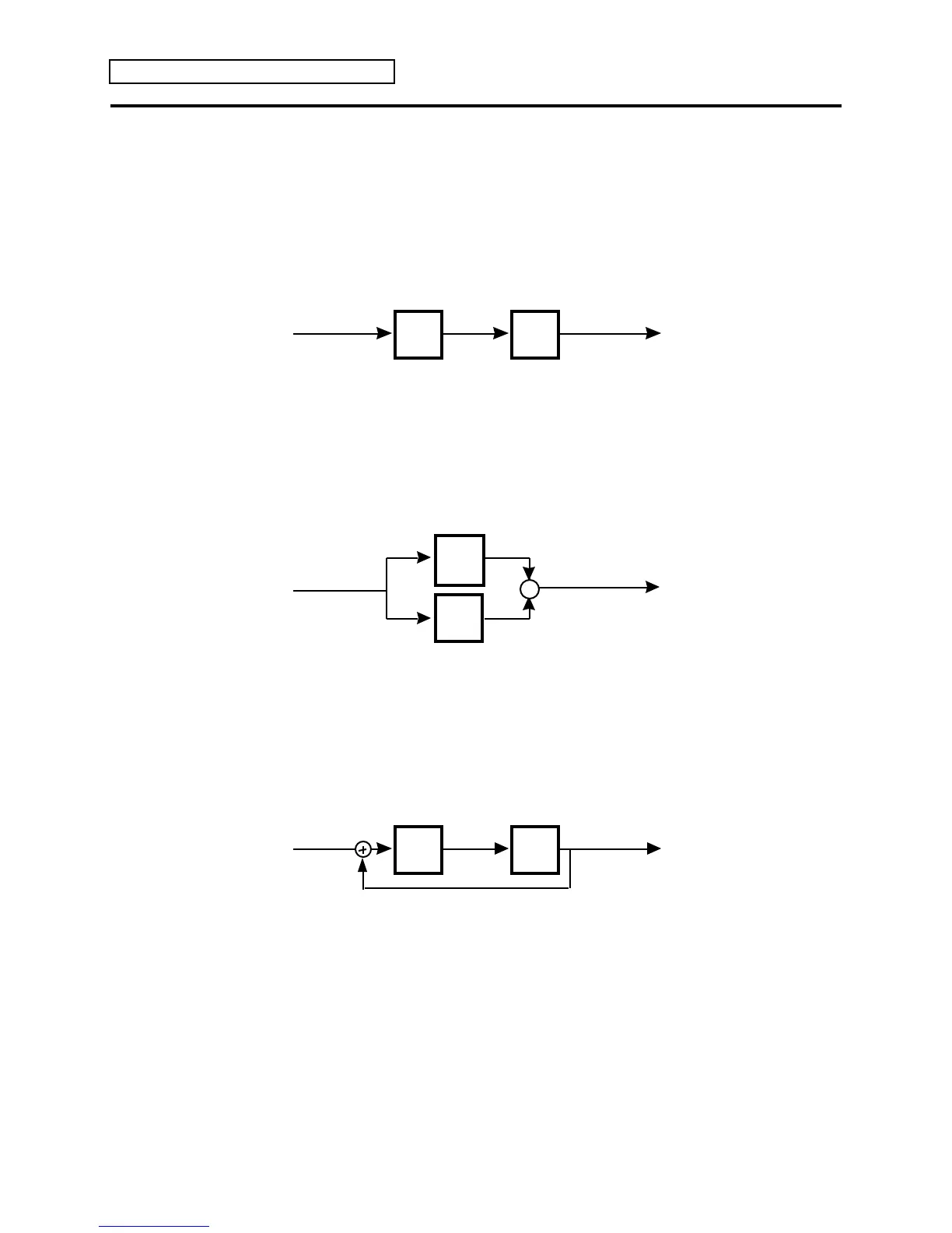
Understanding Serial, Parallel and Feedback Signal Routing
When we speak of connecting units together, we are usually referring to one of three types of
signal routing, serial, parallel, or feedback. It is very important to understand the difference
between these concepts.
Serial Routing
Serial routing means the input signal is routed through the first unit before being sent to the input
of the second unit.
Input Output
1st
Unit
2nd
Unit
Signal Signal
This is a serial signal routing between two units:
If, for example, the first unit is a chorus, and the second a reverb, you have the signal first going
through the chorus, then into the reverb. As a result, you would hear the chorused sound with
reverb applied to it.
Parallel Routing
Parallel routing means the same input signal is routed separately to inputs of both units, and then
their outputs are mixed together.
Input
1st
Unit
2nd
Unit
Signal Signal
This is a parallel signal routing between two units:
Output
+
In this example, if the first unit is a chorus, and the second a reverb, you would hear the chorused
sound and a sound with reverb, but the chorused sound would not have reverb on it, and the
sound coming out of the reverb would not have chorusing.
Feedback Routing
Feedback routing (shown by a
symbol) is similar to serial routing, with the addition of a
feedback signal. See Section 3 — Config Parameters for more on feedback routing.
Input Output
1st
Unit
2nd
Unit
Signal Signal
This is a feedback signal routing between two units:
In this example, if the first unit is a chorus, and the second a reverb, you have the signal first
going through the chorus, then into the reverb. There is then an additional tap that sends the
processed signal back into the beginning of the first unit (the chorus).

Table of Contents

Question and Answer IconNeed help?

Do you have a question about the ENSONIQ DP/4+ and is the answer not in the manual?

ENSONIQ DP/4+ Specifications

General IconGeneral
BrandENSONIQ
ModelDP/4+
CategoryRecording Equipment
LanguageEnglish

Summary

Section 1 — Controls & Basic Functions

Front Panel Controls

Details the functions of all controls on the DP/4+'s front panel.

Rear Panel Connections

Describes the various input, output, and control jacks on the rear panel.

DP/4+ RULES

Explains basic operational rules like setting levels and switches.

DP/4+ Modes

Explains the three operational modes: Select, Edit, and System•MIDI.

Replacing the Algorithm in a Single Unit

Instructions on how to change algorithms within a unit.

Section 2 — Algorithms

EQ - DDL - WITH LFO

Combines EQ, stereo delay, and LFO modulation for various effects.

EQ - Flanger - DDL

Combines EQ, flanger, and digital delay for a "jet aircraft woosh" effect.

EQ - Panner - DDL

Combines EQ, panning, and digital delay for a ping-pong effect.

EXPANDER

Controls dynamic range by reducing signal levels below a threshold.

GUITAR AMP 1, GUITAR AMP 2

Emulates warm tube guitar amplifier sounds with distortion characteristics.

GUITAR AMP 3

Emulates a tube amplifier with inverse expander and bright distortion.

GUITAR AMP 4

Emulates vintage class "A" tube amplifier sounds with symmetrical distortion.

ROTATING SPEAKER

Emulates the classic rotating speaker sound with tunable distortion.

SPEAKER CABINET

Simulates the warm sound of an open-back speaker cabinet.

VCF - DISTORT 1

Combines voltage control filter and distortion for Distortion, Wah-wah, Auto-wah.

VOCODER

Analyzes a source's frequency spectrum and applies it to a pitched sound.

Section 3 — Config Parameters

Section 5 — Storage

Saving Presets

Step-by-step guide to naming and saving presets to RAM.

Section 6 — Presets

Quick Steps to Hear Presets

Provides concise steps to select and listen to presets.

Glossary

Config

Defines Config for signal routing and input handling.

Preset

Combination of algorithms and parameter settings for effects.

Vocoder

Analyzes a source's frequency spectrum and applies it to a pitched sound.

Parameter Reference

VCF-Distort 1

Lists parameters for the VCF-Distort 1 algorithm.

VCF - Distort 2

Lists parameters for the VCF-Distort 2 algorithm.

Vocal Remover

Lists parameters for the Vocal Remover algorithm.

Related product manuals