Section 1 — Controls & Basic Functions
2 ENSONIQ DP/4+ Reference Manual
3 42
Mute Outputs
1 2 3 4
outputs
inputs
Mic Gain
Copy Undo
phones
input 1
inst/mic
Write Cancel
peak
signal
MIDI
rear input 1 off
push
.00
51 6 7 98
paralle
DP/
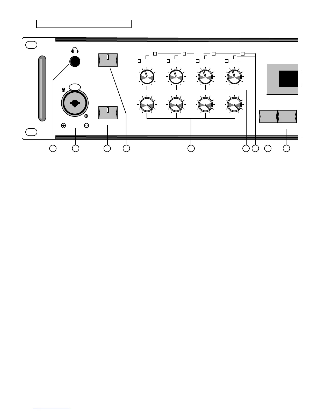
Front Panel Controls
1. Phones
Plug headphones into this 1/4” stereo jack to listen to the
DP/4+ in stereo. The signal going to this jack is from the
sum of all four rear outputs, even if they are not
connected. The 4 rear outputs are mapped to the stereo
headphone as follows: 1 and 3 are mostly to the left; 2
and 4 are mostly to the right. Headphone volume is
controlled by the Output Knobs. Plugging headphones
into this jack does not turn off the audio in the outputs.
☞ Warning: The headphone output circuit is designed
to minimize the volume differences between low and
high impedance headphones. Because some
headphones are more efficient than others, set the
Output Knobs accordingly — high output volume levels
could damage your hearing.
2. Input 1 — (inst/mic)
This combination balanced XLR mic/unbalanced 1/4”
mono input jack is for connecting a guitar, microphone,
or any high or low impedance instrument. This jack is
routed to the same input circuitry as the Input 1 jack
located on the rear panel, and is electrically equivalent.
3. Mic Gain — (rear input 1 off)
This activates the XLR Mic (microphone) input and
supplies mic gain to both the Mic and Instrument inputs.
When set to Instrument (LED off):
The XLR Mic Input is disabled.
The 1/4” front panel Instrument input is enabled.
Rear panel Input 1 is overridden and disabled when
the 1/4” front panel Instrument input is connected.
When set to Mic (LED on):
The XLR Mic Input is enabled.
Mic Gain will be supplied to the XLR Mic input.
The 1/4” front panel Instrument input is enabled.
Mic Gain is not supplied to the 1/4” front panel
Instrument input.
Rear panel Input 1 is overridden and disabled.
4. Mute Outputs — (inst/mic)
This button is used to mute the rear panel output jacks.
When the LED is on, the output jacks are muted, but the
headphone output remains active.
5. Output Knobs
The four Output Knobs control the output level of each
channel. If separate signals are being processed in the
ENSONIQ DP/4+, these knobs will control the “mix-
down” volumes. The maximum output level is +19 dBu.
6. Input Knobs
These four input knobs control the gain applied to the
input signals. The input circuitry is designed to work with
signals ranging from -34.6 dBV to +22 dBu. Use these
knobs to set each input to the optimal level for the signal
you are feeding into it.
7. Signal/Peak LEDs
The three LEDs above each knob indicate the level of
the input signal being fed into the Analog-to-Digital
Converters (ADCs).
• The Signal LED (green) will light when a low level
signal (-30dB) is present at the input. Extremely low
level input signals may not trigger this LED.
• The middle LED (yellow) will light at -12dB.
• The Peak LED (red) will light when the incoming
signal reaches -6dB below the ADC clipping point.
For optimal level, adjust the Input Knob so that the
Peak LED flashes only occasionally. Note that the Peak
LEDs indicate the levels of the input signals only and will
not reflect clipping in the digital processing stages.
8. Write•Copy Button
The {WRITE"COPY} button is used to save or copy
presets to the DP/4+’s internal RAM memory.