EasyManua.ls Logo

ENSONIQ DP/4+ User Manual

ENSONIQ DP/4+
199 pages
To Next Page IconTo Next Page
To Previous Page IconTo Previous Page
Page #75 background imageLoading...
Page #75 background image
Section 2 — Algorithms
ENSONIQ DP/4+ Reference Manual 59
LARGE PLATE
A plate reverb takes the vibrations from a metal plate and uses them to create a metallic sounding
reverb. Large plate reverbs are often used to enhance a vocalist’s performance.
Large Plate simulates a larger plate reverb.
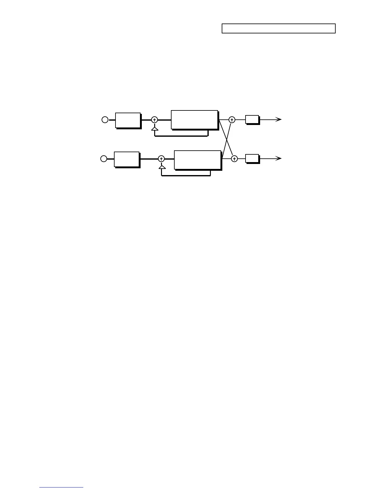
Large Plate Reverb Signal Routing
Right
Diffuser
Diffuser
L
LPF
Main
Outputs
Left
LPF
R
Definition
(Decay Diffuser)
Definition
(Decay Diffuser)
The two plate reverb algorithms share exactly the same signal routing topology. The internal
values of the components (not user programmable) differentiate the large and small plate
reverbs. The signal goes directly through the diffusers which smear the signal. The signal is then
routed to a larger decay diffuser, known as Definition, and is diffused over a period of time
(creating a decay). The signal is then routed to the output, and then goes through a low pass
filter. There is a parameter that controls the decay time of both the left and right signals (shown
as triangles above). This signal is then routed back into the definition. There is also an external
dry signal (not shown) that goes directly from the input to the output and is controlled with the
mix parameter (01).
01 — Mix
02 — Volume
See the descriptions under the Mix and Volume Parameters, found earlier in this section.
03 — Decay Range: 0.40 to 140.0 sec.
Controls the amount of time it takes for the reverberation to decay. High values of decay sound
good on these algorithms.
04 — Predelay Time Range: 0 to 430 ms
Controls the amount of time it takes for the input signal to be presented to the plate reverb. A
value of 0 would offer no delay.
05 — HF Damping Range: 00 to 99
Increasing the value of this parameter will gradually filter out increasing amounts of high
frequency energy. Higher values yield an abrupt decay. This parameter controls the cut off of a
low pass filter in series with the decay within the definition.
06 — HF Bandwidth Range: 01 to 99
This parameter acts as a low pass filter on the output of the plate reverbs, controlling the amount
of high frequencies present. The higher the setting, the more high frequencies are allowed to pass
through, offering a brighter ringing sound. Some interesting effects can be created by using a
mod controller over a large range.

Table of Contents

Question and Answer IconNeed help?

Do you have a question about the ENSONIQ DP/4+ and is the answer not in the manual?

ENSONIQ DP/4+ Specifications

General IconGeneral
BrandENSONIQ
ModelDP/4+
CategoryRecording Equipment
LanguageEnglish

Summary

Section 1 — Controls & Basic Functions

Front Panel Controls

Details the functions of all controls on the DP/4+'s front panel.

Rear Panel Connections

Describes the various input, output, and control jacks on the rear panel.

DP/4+ RULES

Explains basic operational rules like setting levels and switches.

DP/4+ Modes

Explains the three operational modes: Select, Edit, and System•MIDI.

Replacing the Algorithm in a Single Unit

Instructions on how to change algorithms within a unit.

Section 2 — Algorithms

EQ - DDL - WITH LFO

Combines EQ, stereo delay, and LFO modulation for various effects.

EQ - Flanger - DDL

Combines EQ, flanger, and digital delay for a "jet aircraft woosh" effect.

EQ - Panner - DDL

Combines EQ, panning, and digital delay for a ping-pong effect.

EXPANDER

Controls dynamic range by reducing signal levels below a threshold.

GUITAR AMP 1, GUITAR AMP 2

Emulates warm tube guitar amplifier sounds with distortion characteristics.

GUITAR AMP 3

Emulates a tube amplifier with inverse expander and bright distortion.

GUITAR AMP 4

Emulates vintage class "A" tube amplifier sounds with symmetrical distortion.

ROTATING SPEAKER

Emulates the classic rotating speaker sound with tunable distortion.

SPEAKER CABINET

Simulates the warm sound of an open-back speaker cabinet.

VCF - DISTORT 1

Combines voltage control filter and distortion for Distortion, Wah-wah, Auto-wah.

VOCODER

Analyzes a source's frequency spectrum and applies it to a pitched sound.

Section 3 — Config Parameters

Section 5 — Storage

Saving Presets

Step-by-step guide to naming and saving presets to RAM.

Section 6 — Presets

Quick Steps to Hear Presets

Provides concise steps to select and listen to presets.

Glossary

Config

Defines Config for signal routing and input handling.

Preset

Combination of algorithms and parameter settings for effects.

Vocoder

Analyzes a source's frequency spectrum and applies it to a pitched sound.

Parameter Reference

VCF-Distort 1

Lists parameters for the VCF-Distort 1 algorithm.

VCF - Distort 2

Lists parameters for the VCF-Distort 2 algorithm.

Vocal Remover

Lists parameters for the Vocal Remover algorithm.

Related product manuals