Connecting to Console Port for Local Management
3-18 Hardware Installation
What Is Needed
Thefollowingisalistofuser‐suppliedDTEinterfacecablesthatmaybeneededtoconnect
theDB9male Consoleportconnectorontheswitch.ThecablesareterminatedbyaDB9
femaleconnectoratoneend,andbyoneofthreetypeconnectorsattheotherend,
dependingon
thetypeconnectionneededfortheremotedevice.Thecables thatmaybe
neededareasfollows:
•DB9female‐to‐DB9female
•DB9female‐to‐DB25female
•DB9female‐to‐DB25male
UsingaDTEmodemDB9female‐to‐DB9femalecable,youcanconnectproducts
equippedwithaDB9DTEmale
consoleporttoanIBMorcompatiblePCrunningaVT
seriesemulationsoftwarepackage.
UsingaDTEmodemDB9female‐to‐DB25 femalecable,youcanconnectproducts
equippedwithaDB9DTEmaleconsoleporttoaVTseriesterminalorVTtypeterminals
runningemulationprogramsforthe
VTseries.
UsingaDTEmodemDB9female‐to‐DB25malecable,youcanconnectproductsequipped
withaDB9DTEmaleconsoleporttoaHayescompatiblemodemthatsupports
9600 baud.
ThecableusedmustconnecttheConsoleportReceivedData,Pin2totheTransmitted
Datapinatthe
otherendofthecable.TheconnectionfromtheConsoleportTr a nsmitted
Data,Pin3(mustbeconnected)totheReceivedDatapincableconnectionattheotherend
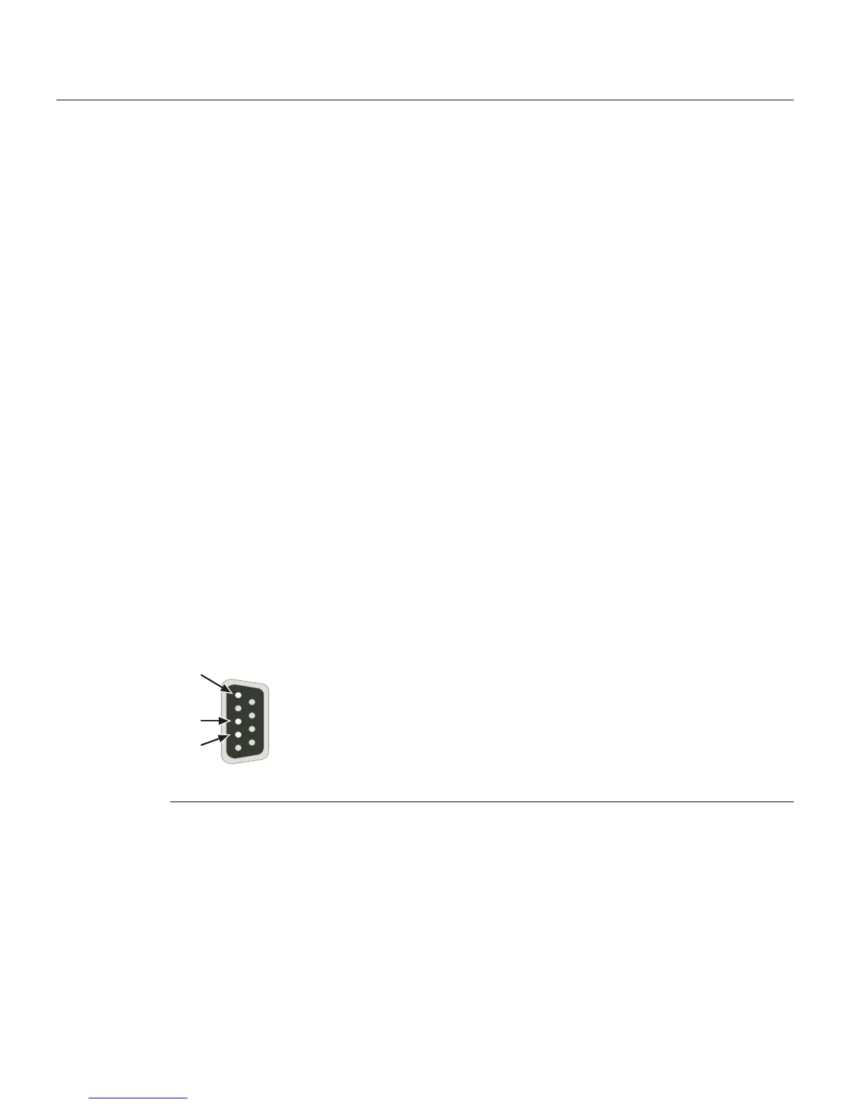
ofthecable.TheDB9ConsoleportpinassignmentsareshowninFigure 3‐10.
Figure 3-10 DB9 Male Console Port Pinout Assignments
1 Pin 2, Received Data (input)
2 Pin 3, Transmitted Data (output)
3 Pin 5, Signal Ground
All other pins not connected.
Â
À
Á
5
1
9
6