Connecting to the Network
SecureStack C2 Installation Guide 3-27
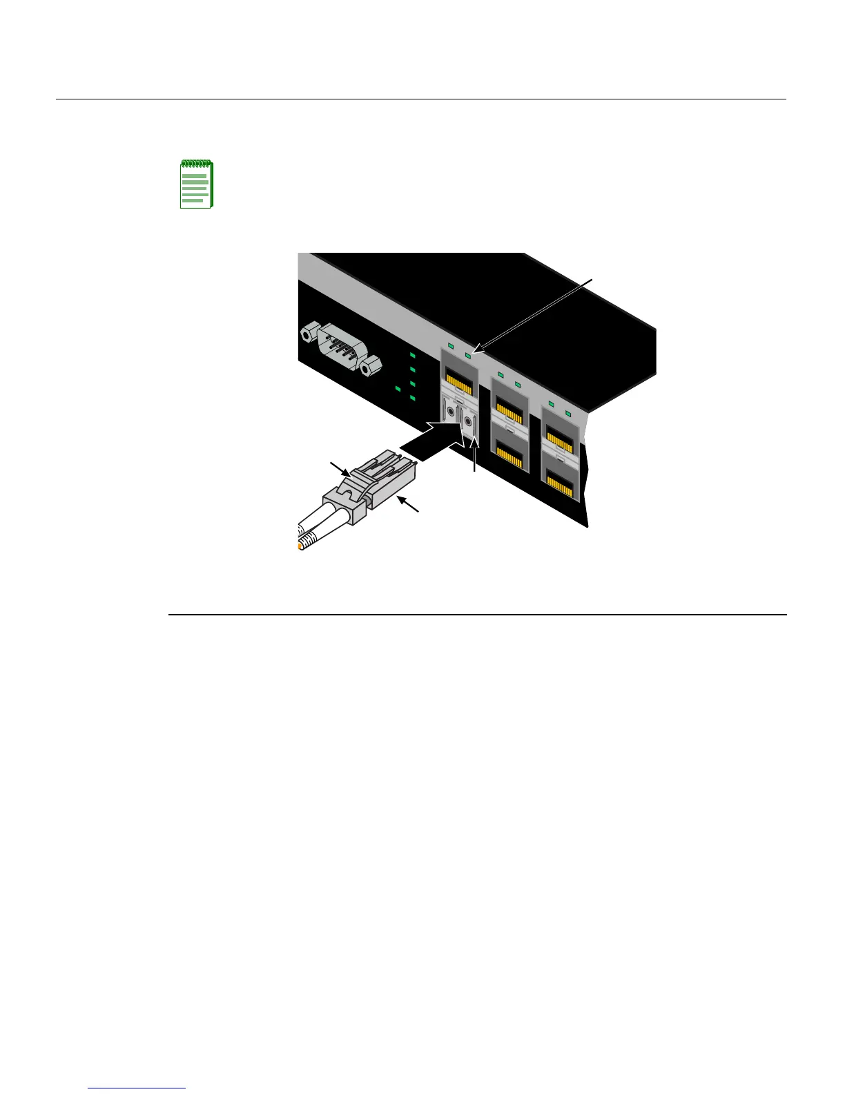
2. InserttheMT‐RJcableconnectorintotheMT‐RJconnectoruntilitclicksintoplace.
Figure 3-19 Cable Connection to MT-RJ Multimode Fiber-Optic Connectors
3. Plugtheotherendofthecableintotheappropriateportontheotherdevice.Some
cablesmaybeterminatedattheotherendwithtwoseparateconnectors,oneforeach
fiber‐opticstrand.In
thiscase,ensurethatthetransmitfiber‐opticstrandisconnected
tothereceiveportandthereceivefiber‐opticstrandtothetransmitport.
4. Verifytha talinkexistsby checkingthattheportLink/ActivityLEDison(blinking
greenorsolidgreen).IftheLink/ActivityLEDisoff,perform
thefollowingstepsuntil
itison:
a. Verifytha tthedeviceattheotherendofthesegmentisONandconnectedtothe
segment.
b. Ifthereareseparatefiber‐opticconnectionsontheotherdevice,checkthe
crossoverofthecables.Swapthecableconnectionsifnecessary.
c. Checkthatthefiber
‐opticconnectionmeetsthedBlossandcablespecifications
outlinedintheCablingGuideformultimodecabling. Toobtainthisdocument,
referto“RelatedDocuments”onpage xiv.
Note: To remove the MT-RJ cable connector, press on its release tab and pull out the
cable connector.
1 Mini-GBIC MT-RJ port connector 3 Release tab
2 MT-RJ cable connector 4 Link/Activity LED
Console
6
5
4
3
2
1
1
2
CPU
UP
RPS
MGR
DOWN
À
Â
Á
Ã