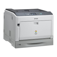
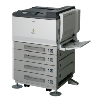
EPSON AcuLaser C1900/AcuLaser C900 Revision B
Troubleshooting Check Points and Remedy for Paper Jam 160
3.4.3 Jam Detection Timing / Action to be Taken
JAM IN MANUAL PAPER FEED AREA
Detection Timing
Solution
Electric parts which may cause paper jam
• Timing Roller Front Sensor (PC2)
• Manual Paper Feed Solenoid (SL1)
• Engine Board (PWB-A)
JAM IN SECONDARY TRANSFER AREA
Detection Timing
Solution
Electric parts which may cause paper jam
• Timing Roller Front Sensor (PC2)
• Fusing Loop Detection Sensor (PC11)
• Engine Board (PWB-A)
Table 3-2. Detection Timing
Category Explanation
Jam detection in
manual paper feed
area
Even on the lapse of a predetermined time after turning on of the
manual paper feed solenoid (SL1), the front end of the paper does not
intercept the light to the timing roller front sensor (PC2).
Size error detection
in MP tray
The light to the timing roller front sensor (PC2) is not transmitted
even on the lapse of a predetermined time after the paper intercepted
the light to the sensor (PC2).
Table 3-3.
Step Action Refer to
WARNING DIAGRAM
Control Signal
1 Initial checking p.159 -
2 Check the operation of PC2 p.162 PC2_ON
3 Check the operation of SL1 p.163 SL1_REM
4 Replace the PWB-A. - -
Table 3-4. Detection Timing
Category Explanation
Jam detection in
secondary transfer
area
The light to the timing roller front sensor (PC2) is not transmitted
even on the lapse of a predetermined time after the paper intercepted
the light to the sensor (PC2).
The light to the fusing loop detection sensor (PC11) is not
intercepted even after the paper has passed the interception position.
Remaining paper
detection in
secondary transfer
area
The light to the timing roller front sensor (PC2) is intercepted when
the main switch is turned on, the door and cover are opened and
closed or a jam or trouble is cleared.
Table 3-5.
Step Action Refer to
WARNING DIAGRAM
Control Signal
1 Initial checking p.159 -
2 Check the operation of PC2 p.162 PC2_ON
3 Check the operation of PC11 p.162 PC11_ON
4 Replace the PWB-A. - -

 Loading...

