EPSON AcuLaser C1900/AcuLaser C900 Revision B
Disassembly and Assembly Printer Main Parts Disassembly and Assembly 201
4.5.19 Fuser Deceleration Drive Assy
1.
Remove the Rear Cover. (p.178)
2.
Remove the Engine Board (PWB-A). (p.184)
3. Remove the Controller Box.
(p188)
4. Release the wiring from the cord holder and remove the Assy Cover.
(2 screws)
(p191)
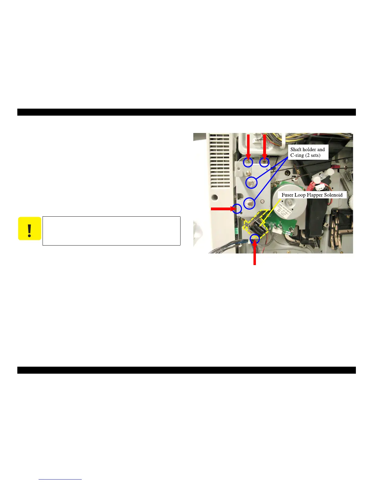
5. Remove the Fuser Loop Flapper Solenoid (SL6). (1 screw)
(p191)
6. Remove the C-rings and shaft holders from the two shafts mounted on the Fuser Loop
Flapper Solenoid. (See
“Figure 4-56 (p.201)”)
7. Remove the Fuser Deceleration Drive Assy. (4 screws)
Figure 4-56. Removing the Fuser Deceleration Drive Assy
C A U T I O N
In installation, make sure that the projection on the frame is engaged
with the guide hole in the Fuser Deceleration Drive Assy properly.