EPSON AcuLaser C1900/AcuLaser C900 Revision B
Disassembly and Assembly Periodical Replacement Parts Removal 176
5. Disconnect the connector from the Power Supply Unit and then remove the wires from
the code folder.
6. Remove the Fuser Unit from the Printer. (2 screws, 2 connectors)
(See
“Figure 4-4 (p.176)”)
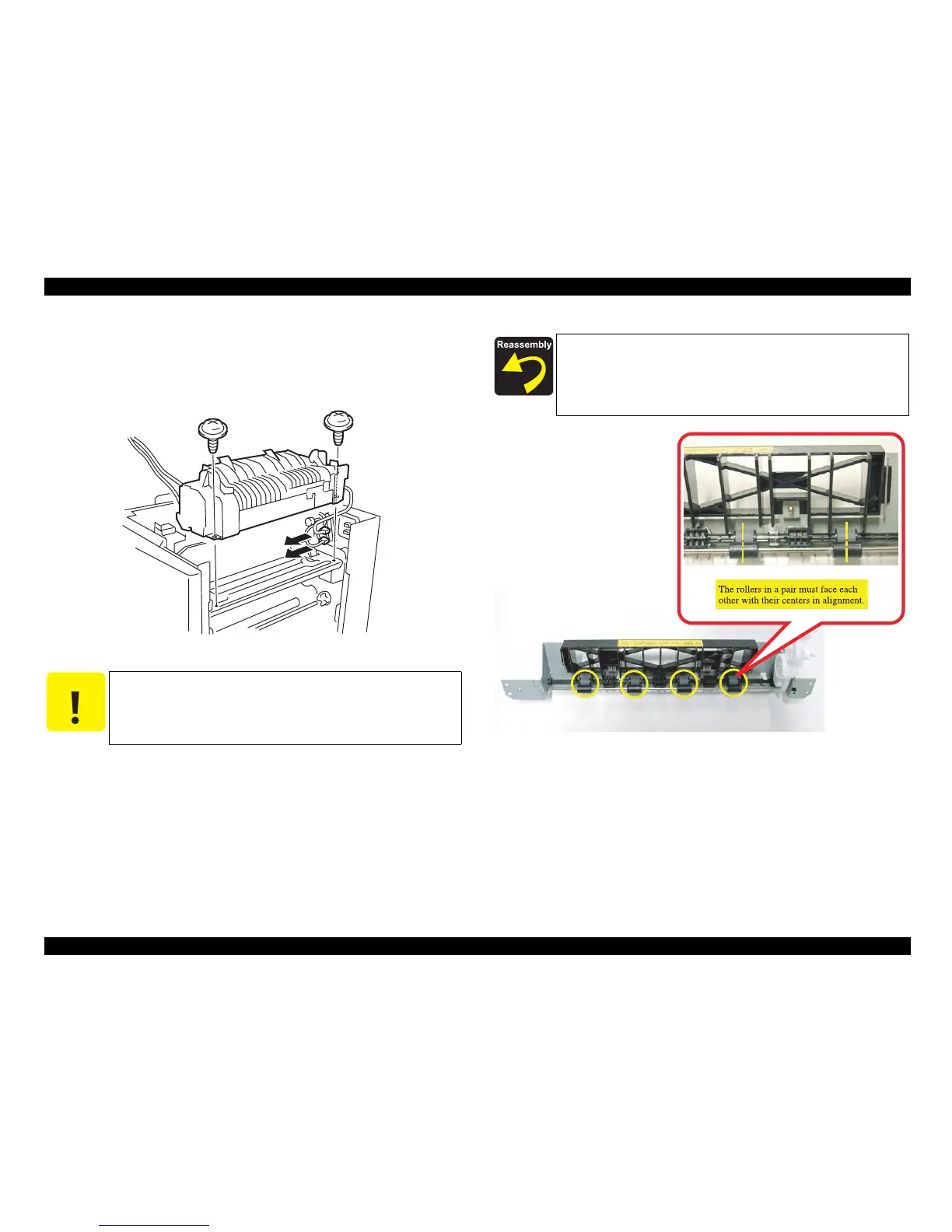
Figure 4-4. Fuser Unit Removal
Figure 4-5. Installing the Fuser Unit Cover
C A U T I O N
wOn the bottom of the Fuser Unit, there is a hook engaged with the
printer body frame. For removal of the Fuser Unit, tilt the front side
of the Fuser Unit rearward and lift it. (In installation, ensure that the
hook is engaged with the printer body frame properly.)
When installing the Fuser Unit Cover, make sure that the black resin
roller and gray rubber roller in a pair face each other with their
centers in alignment. (Unless the rollers are in alignment, paper can
not be fed properly, thus causing a paper jam.) (See
“Figure 4-5
(p.176)”)