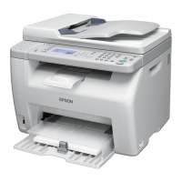
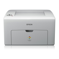
EPSON AcuLaser C1900/AcuLaser C900 Revision B
19
Chapter 2 Operating Principles
2.1 Mechanism Overview.......................................................................................... 88
2.1.1 Locations of Electric Parts.......................................................................... 89
2.2 Operation Sequence............................................................................................. 92
2.3 Image Stabilization Control................................................................................. 93
2.3.1 Execution Conditions for Image Stabilization Control (Only for AcuLaser
C900) ......................................................................................................... 95
2.3.2 Engine Restrictions..................................................................................... 96
2.4 Description of Mechanisms................................................................................. 97
2.4.1 Paper Path ................................................................................................... 97
2.4.2 Photoconductor Unit................................................................................... 98
2.4.2.1 OPC Drum........................................................................................... 98
2.4.2.2 Charging Process................................................................................. 99
2.4.3 Exposure Process...................................................................................... 100
2.4.4 Development Process................................................................................ 101
2.4.4.1 Toner Cartridge Rack ........................................................................ 101
2.4.4.2 Development Position ....................................................................... 102
2.4.4.3 Toner Cartridge ................................................................................. 103
2.4.5 Transfer Process........................................................................................ 105
2.4.5.1 Transfer Belt Unit.............................................................................. 105
2.4.5.2 Secondary Transfer Roller Cleaning ................................................. 106
2.4.5.3 Transfer Belt Cleaner Mechanism..................................................... 107
2.4.5.4 Waste Toner Box............................................................................... 108
2.4.5.5 Waste Toner Box Detection .............................................................. 108
2.4.6 Fusing Process .......................................................................................... 109
2.4.6.1 Fuser Unit.......................................................................................... 109
2.4.6.2 Fusing Loop Control ......................................................................... 110
2.4.6.3 Fusing Temperature Control ............................................................. 111
2.4.7 Paper Feed Mechanism............................................................................. 113
2.4.7.1 MP Tray............................................................................................. 113
2.4.7.2 500-sheet Cassette Unit (Option) ...................................................... 114
2.4.8 Other Mechanisms.................................................................................... 115
2.4.8.1 Duplex Unit (option) ......................................................................... 115
2.5 Controller Board Operating Principles.............................................................. 118
Chapter 3 Troubleshooting
3.1 Overview ........................................................................................................... 123
3.2 Status Display (AcuLaser C1900)..................................................................... 124
3.2.1 Service Call Error Status .......................................................................... 124
3.2.1.1 Details of Service Call Errors and Remedy ...................................... 125
3.2.2 Printer Status............................................................................................. 131
3.2.3 Details of Status Messages and Treatment Method.................................. 133
3.2.4 Details of Error Status and Remedy ......................................................... 135
3.2.5 Details of Warning Status and Remedy.................................................... 140
3.3 Status Display (AcuLaser C900)....................................................................... 143
3.3.1 Service Call Error Status .......................................................................... 143
3.3.1.1 Details of Service Call Errors and Remedy ...................................... 145
3.3.2 Printer Status............................................................................................. 151
3.3.3 Details of Status Messages and Treatment Method.................................. 152
3.3.4 Details of Error Status and Remedy ......................................................... 153
3.3.5 Details of Warning Status and Remedy.................................................... 156
3.4 Check Points and Remedy for Paper Jam ......................................................... 159
3.4.1 Initial Checking ........................................................................................ 159
3.4.2 Locations of Jam Detection Sensors......................................................... 159
3.4.3 Jam Detection Timing / Action to be Taken............................................. 160
3.4.4 Checking Method for Electric Parts ......................................................... 162
3.5 Details of Print Quality Trouble and Remedy................................................... 164
Chapter 4 Disassembly and Assembly
4.1 Overview ........................................................................................................... 167
4.1.1 Precautions................................................................................................ 167
4.1.2 Tools ......................................................................................................... 169
4.1.3 Screws....................................................................................................... 169
4.2 Main Unit Disassembly..................................................................................... 170
4.2.1 Before Disassembling the Printer ............................................................. 172
4.2.1.1 Toner Cartridge Removal.................................................................. 172
4.2.1.2 Removal of Other Units .................................................................... 173
4.3 Periodical Replacement Parts Removal ............................................................ 175
4.3.1 Secondary Transfer Roller........................................................................ 175
4.3.2 Fuser Unit ................................................................................................. 175
4.4 Cover Removal.................................................................................................. 177
4.4.1 Upper Front Cover.................................................................................... 177
4.4.2 Top Cover................................................................................................. 177
4.4.3 Front Door ................................................................................................ 178
4.4.4 Rear Cover................................................................................................ 178
4.4.5 Upper Rear Cover..................................................................................... 178
 Loading...

