EPSON AcuLaser C1900/AcuLaser C900 Revision B
Disassembly and Assembly Printer Main Parts Disassembly and Assembly 195
4. Remove the Release Lever, the Fusing Front Guide Plate and the Fusing Rear Guide
Plate. (2 screws) (See
“Figure 4-41 (p.195)”)
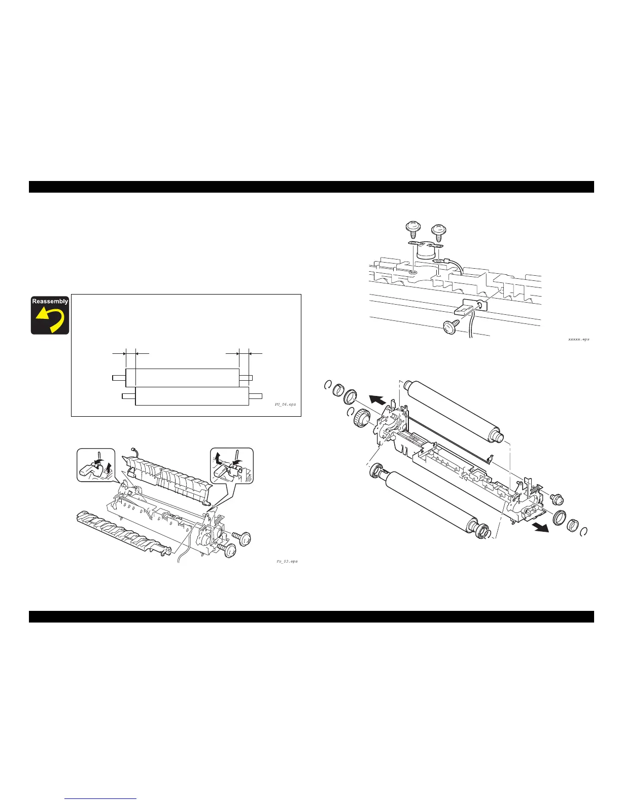
5. Remove the Thermistor (TH1) and the Thermostat (TS1). (3 screws)
(See
“Figure 4-42 (p.195)”)
6. Remove the Fusing Roller and Pressure Roller. (screws, E-rings, C-rings)
(See
“Figure 4-43 (p.195)”)
Figure 4-41. Fusing Guide Plate Removal
Figure 4-42. Thermistor / Thermostat Removal
Figure 4-43. Heat Roller Removal
Install the Fusing Roller and Pressure Roller so that they are not out
of alignment excessively.
Misalignment:
±
3 mm maximum
3 mm max. 3 mm max.
Pressure Roller
Fusing Roller
 Loading...


