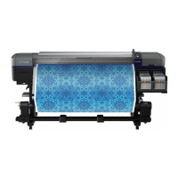
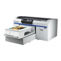
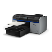
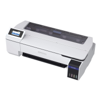
Figure 3-6. Ink System Mechanism
Pump Cap Unit 2 (p. 177)
Includes the wiper section and the
sucking section, and maintains the
Print Head.
Ink Holder 1 (p. 183)
Stores ink cartridges and includes the following
mechanism and parts.
• Pressure mechanism (Sensor/Motor)
• Ink Level Sensor
• LED
• Cartridge Cover Sensor
•SUB-G Board
Ink Tube (p. 196)
Wiper (p. 100)
Cleans the nozzle surface of the Print Head.
Wiper Cleaner (p. 100)
Wipes off ink attached on the Wiper.
Ink Holder 2 (p. 189)
Composed of the parts and mechanism
equivalent to Ink Holder 1.
Ink Tank (p207)
Pump Cap Unit 1 (p. 170)
Includes the wiper section
and the sucking section,
flushing section and
maintains the Print Head.
 Loading...
