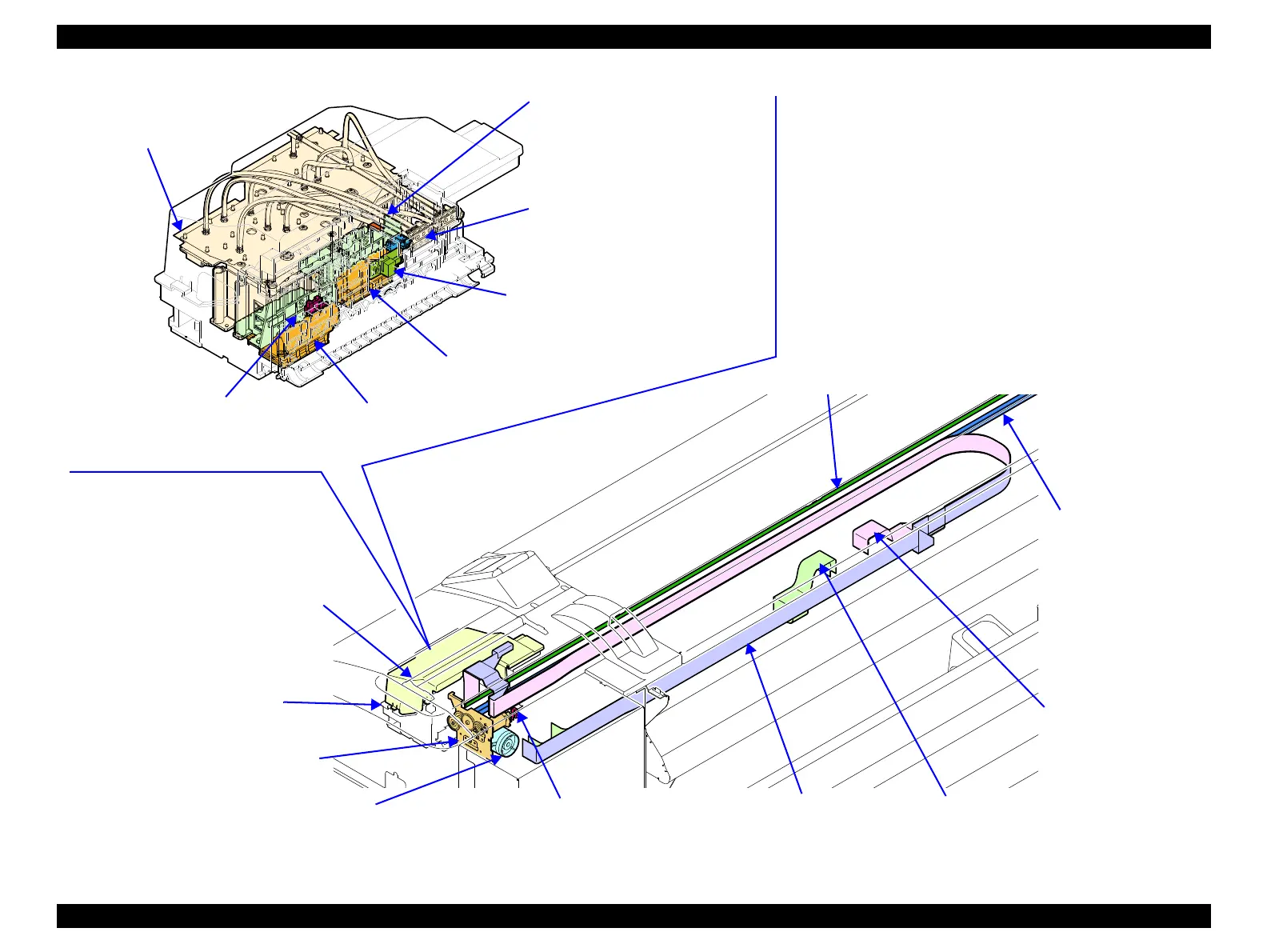
Figure 3-5. Carriage Mechanism
CR Cover (p. 139)
Duct CR (p. 140)
Print Head 1 (p144)
CR Scale (p. 157)
Head Relay FFC (p. 153) (x4)
CR Timing Belt (p. 159)
CR Motor (p. 161)
The motor to drive the CR Unit.
CR HP Sensor (p. 164)
Detects the home position of the CR Unit.
CR Encoder (p. 166)
Detects the pattern of the CR Scale to control
the position of the CR Unit.
APG Motor (p. 167)
PG HP Sensor (p. 169)
Detects the origin position of the
platen gap.
PW Sensor (p. 204)
Detects the width of paper on the
platen. This is a reflective photo
interrupter and detects the difference of
the amount of reflection between paper
(white) and the platen (black).
CR Unit (p. 200)
Head FFC (p. 150) (x4)
CR FFC (p. 155)
IM Sensor (p. 206)
Reads print patterns in the following
adjustments.
• Head Slant Auto Adjustment (PF
direction)
Print Head 2 (p144)

 Loading...


