SC-F9200 Series Revision B
DISASSEMBLY & ASSEMBLY Disassembly and Assembly Procedure 153
SE Group Confidential (Related Staff Only)
3.4.5.5 Head Relay FFC
1. Remove the Media Loading Lever. (p210)
2. Remove the Panel Unit. (p101)
3. Remove the Right Upper Cover. (p103)
4. Remove the Left Rear Cover. (p110)
5. Remove the Left Upper Cover. (p111)
6. Remove the Upper Cover. (p116)
7. Remove the Board Box Cover. (p117)
8. Remove the Cover. (See Step 14 in “3.4.5.4 Head FFC” (P. 150))
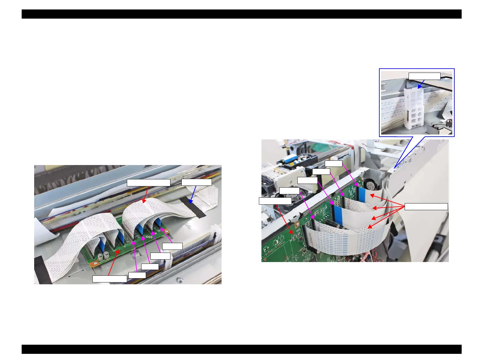
9. Disconnect the Head Relay FFCs from the connectors (CN400, CN401, CN402,
CN403) on the Sub-D Board.
10. Remove the acetate tape, and release the Head Relay FFCs from the FFC clamp.
Figure 3-91. Removing the Head Relay FFC
11. Disconnect the Head Relay FFCs from the connectors (CN400, CN401, CN402,
CN403) on the Main Board.
12. Pull out the Head Relay FFCs from the main body.
Figure 3-92. Removing the Head Relay FFC
Head Relay FFC
Sub-D Board
CN400
Acetate tape
CN401
CN402
CN403
Main Board
CN400
CN401
CN402
CN403
Head Relay FFCs

 Loading...


