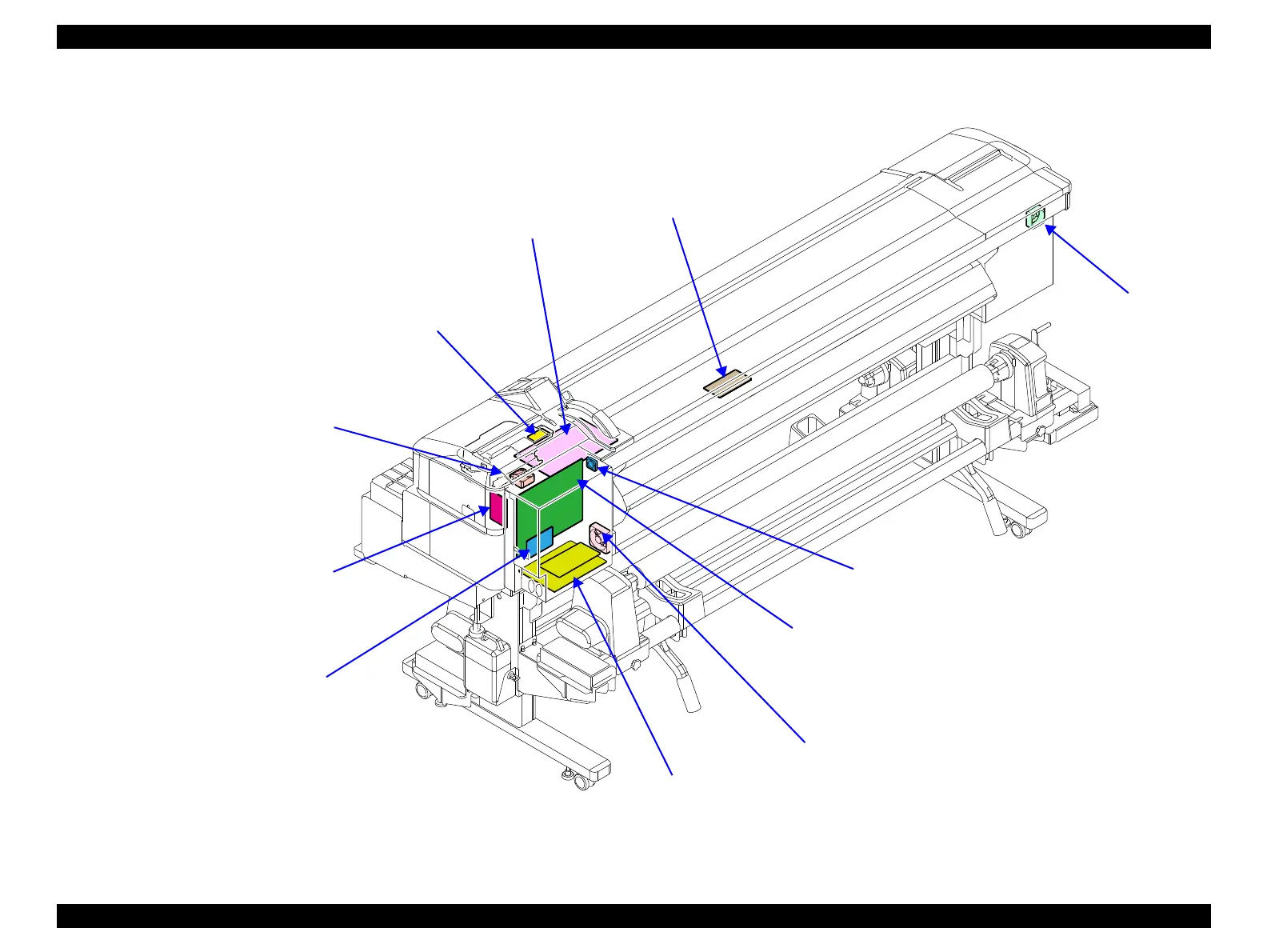
Figure 3-4. Electric Circuit Components
Main Board (p. 123)
• Communicates with the computer.
• Processes received data.
• Controls the printer mechanism.
• Stores the correction values and various counters.
Main-B Board (p. 124)
Communicates across a network.
PSH Board/PSH-B Board (p. 125)
Generates the DC voltage for this printer from the AC power supply.
Sub-D Board (p. 132)
Relays the connection between the Main
Board and the Print Head.
Sub-E Board (p. 133)
Controls heaters.
Sub-M Board (p. 134)
Relays the connection between the
Main Board and the CR Motor.
Box Cooling Fan (p. 135)
Cools the air inside the Power Supply
Board Box.
Sub Board (p. 131)
Relays the connection between the Main Board and
electric parts/components. See “6.1 Block Wiring
Diagram (p390)” for specific connections to the
concerning parts/components.
Power Supply Board Cooling Fan (p. 137)
CR Motor Cooling Fan
(p. 163)
PF Motor Cooling Fan
(p. 214)

 Loading...


