B
ACDEFGSERVICE
17
D
Installing the Flue
NOTE: The appliance is designed to operate using the approved flexible flue supplied by Escea. Using
other brands of flue may aect the appliance warranty.
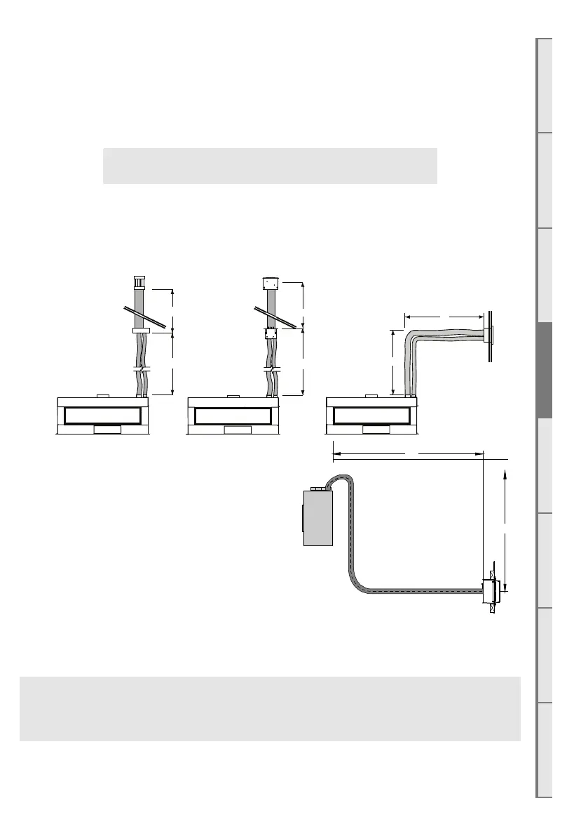
D1 Flue Configuration (For less than 4m length)
If your flue system is less than 4m long (as shown in the diagrams below), then a simple flexible
flue is required. if you wish to install a longer flue run of up to 12m, see section D2 on page
18.
X
Y
X + Y = 4m MAX
= 0.6m MIN
4m MAX
1.2m Co-axial Flue
Vertical PowerFlue
Cowl (Duravent)
4m MAX
1.2m F-F Liner
UVP-Internal Cowl
NOTE: You must provide sucient access to the
powerflue to enable it to be serviced in the future.
This means that the fan unit must have sucient
access to allow it to be replaced if necessary.
The flue must be securely fixed and adequately
supported by brackets fastened to the building
structure at suitable points to ensure the stability
of the flue system.
Any joints within the flue system must be sealed
adequately with a sealing agent used if necessary. The flue system for the DX1500 / DX1000 is
zero rated, so no spaces are required between the flue and any timber framing.
□
ONLY USE ESCEA APPROVED FLUE COMPONENTS
X
Y
X + Y Maximum = 4m
Y Maximum = 1.5m
Y Minimum = 0m
X Maximum = 4m
X Minimum = 0m
X + Y Minimum = 0.6m
NOTE: All sections of horizontal ue, if exible, must be sloped back toward the re at
a rate of no less than 20mm per metre, to allow any condensation to run back into the
appliance.