B
A C D E F G SERVICE
8
A
Installation Process and Product Description
A1 Product Description
The Escea DX1500 / DX1000 gas fire is a direct vent (fan draught balanced flue), room sealed gas
appliance designed to be built into a cavity. This appliance is flued using a co-linear flexible aluminium
flue connected to a powerflue terminal.
The hot air from the gas fire is transferred to the room via 250mm ID / 300 mm OD ducting.
The user will control their fire with the Radio Frequency (RF) remote that will normally be left in its
wall mount cradle. In addition to the RF remote it has a single auxiliary On/O button on the unit.
When not in operation it is in a standby mode unless it is physically isolated from the mains supply.
To access the product Dataplate, first remove the fireplace glass, any fuelbed media, the burners, and
the firebox base. An access panel is located to the side of the bottom of the firebox; the dataplate is
located underneath this access panel.
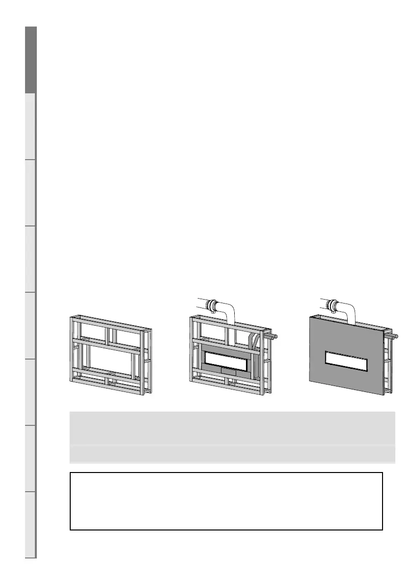
A2 Recommended Installation Process
The following diagram illustrates the steps required to install your gas fire, and the trades required at
each stage.
The sequence in which you choose to do these tasks will vary depending on your individual installation.
Please read these instructions carefully before proceeding with the installation. Leave the installation
of the optional fascia panels until the very end of the installation and commissioning to avoid damage
to the fascia panels.
Create the Cavity Install electrical / gas
connections, ue system, and
replace
Finish installation and t
fascia
Section B Section C, D Section F
Important: Installations that are not specifically outlined in this manual
should be referred to the Escea Architectural Advisory Team.
Please email aa@escea.com
To ensure that your installation is fully complete, please use the “Installation Checklist” on page 45.