B
A C D E F G SERVICE
18
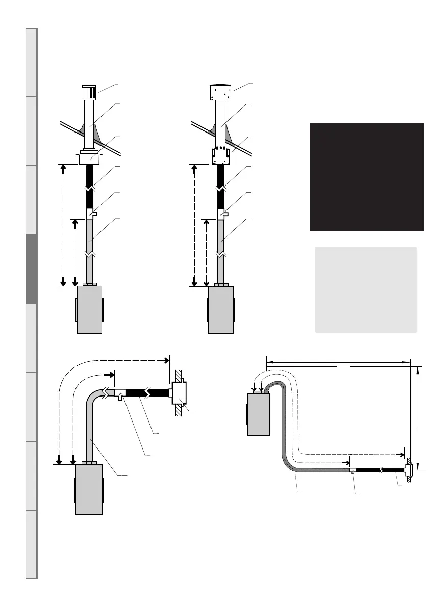
D2 Flue Configuration (For more than 4m length)
If your flue system is greater than 4m long (as shown in diagrams below), then a flexible flue
with condensate trap and rigid PolyPro tube flue lengths is required. (For less than 4m flue runs,
see section D1 on page 17).
4m
Ø80mm / Ø100mm
Flexible Flue
1.2m Co-axial Flue
(Duravent)
Vertical Powerue
Enclosure
12m MAX
Ø100mm
Condensate Trap
Ø80mm / Ø100mm
PP Tube
Vertical PowerFlue
Cowl (Duravent)
4m
ESCEA WALL
TERMINAL
12m MAX
Ø80mm / Ø100mm
PP Tube
Ø100mm
Condensate Trap
Ø80mm / Ø100mm
Flexible Flue
4m
Ø80mm / Ø100mm
Flexible Flue
1.2m F-F Liner
UVP Fan Unit
12m MAX
Ø100mm
Condensate Trap
Ø80mm / Ø100mm
PP Tube
UVP Cowl
FOR MORE INFORMATION ON
INSTALLATION OF THE POLYPRO FLUE,
SEE ‘POLY PRO FLUE INSTALLATION
INSTRUCTIONS’ AVAILABLE ON:
WWW.ESCEA.COM
OR SUPPLIED WITH THE FLUE.
FOR POLY PRO COMPONENT GUIDES,
THESE ARE AVAILABLE ON:
WWW.ESCEA.COM
TITLED:
HORIZONTAL FLUE COMPONENT GUIDE
&
VERTICAL FLUE COMPONENT GUIDE
Y
X + Y Maximum = 12m
Y Maximum = 1.5m
Y Minimum = 0m
X Maximum = 12m
X Minimum = 0m
X + Y Minimum = 0.6m
4m
12m MAX
Ø80mm / Ø100mm
Flexible Flue
Ø100mm
Ø80mm /
Ø100mm
PP Tube
Note: All sections of
horizontal ue, if exible,
must be sloped back
toward the re at a rate
of no less than 20mm
per metre, to allow any
condensation to run back
into the appliance.