B
ACDEFGSERVICE
33
Remove the ‘engine’ by lifting up and to the left. This is still connected internally to the gas hose
and power cables. Place engine just to the left within firebox as shown.
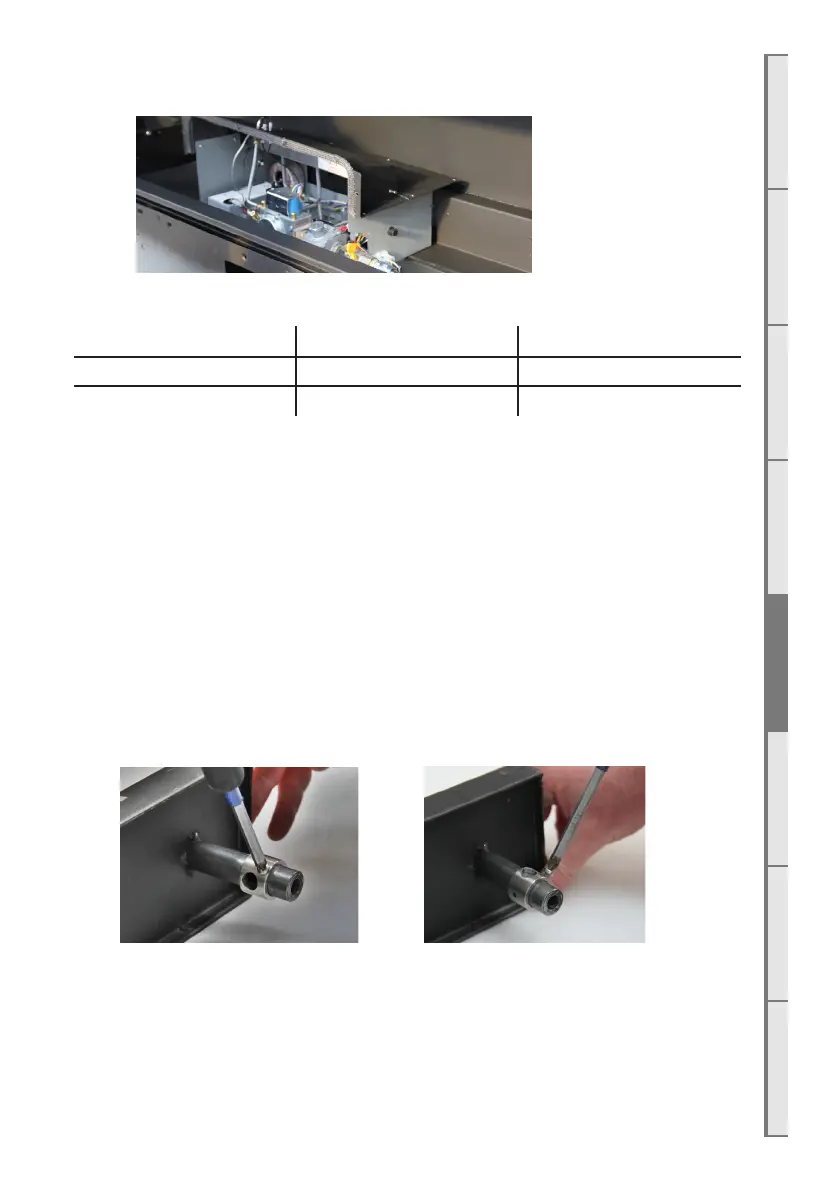
Step 4: Change the two main burner jets with the jets supplied in kitset.
DX1500 DX1000
NG (Both jets) Ø2.3mm Ø1.95mm
Propane / ULPG (Both jets) Ø1.3mm Ø1.10mm
Step 5: Remove the regulator screw cap and screw out the nylon adjuster screw to remove
the existing spring. Replace the spring with the purple spring supplied in the conversion kit and
reassemble the regulator.
Step 6: Cover the existing gas type label (located on underside of hatch shown in
section C4 on page 16) with the new gas type label supplied in kitset. Ensure the serial
number and the date of manufacture are still visible. Write your name, company (if appropriate)
and the date of conversion on the new label with permanent marker.
Step 7: Place the engine back into firebox. Take care not to pinch any wires. Don’t replace the
screws at this stage to make it easier to remove the engine and place manometer hoses.
Step 8: The burner tubes on both burners have convertible collars. Ensure the collars on both
are set to the correct orientation. Place both burners into position.
ULPG/Propane NG
11mm hole exposed 3.5mm hole exposed