IP Server 900 Programming Manual Function 2: CO line programming
E.2
CO ring assignments can include the following Esi-Link
1
remote location destinations:
• Location ID (7xx) + department
• Location ID (7xx) + extension
• Location ID (7xx) + mailbox
Default answer ring assignment for CO lines: ID1.
• The lines installed via TI can be loop, ground, E & M, or DID.
• All CO lines are programmed to route callers during the day mode and then can be programmed to route
callers differently during the night mode. The display will indicate D (for day) or N (for night) to show
which mode is currently being programmed. Lines that are to be programmed alike can be grouped to
simplify programming.
Programming examples
Here are two examples of how to implement this programming; each shows a completed programming
worksheet. Example 1 is simplified, to serve as an illustration for those installations not using Esi-Link; while
Example 2 depicts an Esi-Link-enabled configuration. In each case, the step numbers correspond to the
explanation in “Function 211: Analog CO line programming,” pp. E.5–E.7.
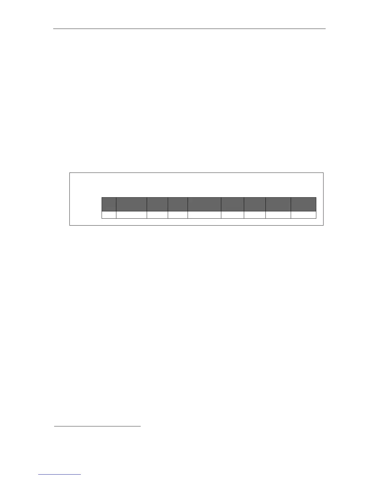
Example 1
(Simplified; non-Esi-Link)
Incoming calls on Line 1 (default name used, here) ring live to extension 100, but are finally answered
by the main greeting after nine rings.
1.
CO
2.
Name
3.
Tenant
4.
Out
5.
Ring tone
6.
Ring 1
Ring 3
Ring 5
Ring 9
1 LINE 1 9 X100 X100 X100 ID 1
(Continued)
1
For more about Esi-Link, see “Function 83: Esi-Link programming,” pp. L.10–L.11.