Chapter 1. Get Started
Power Supply Options There are three mutually exclusive ways to provide power to the board:
• USB-to-UART Port and ESP32-S2 USB Port (either one or both), default power supply (recommended)
• 5V and G (GND) pins
• 3V3 and G (GND) pins
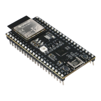
Header Block The two tables below provide the Name and Function of the pin headers on both sides of the board
(J1 and J3). The pin header names are shown in ESP32-S2-DevKitC-1 - front. The numbering is the same as in the
ESP32-S2-DevKitC-1 Schematic (PDF).
J1
No. Name Type
1
Function
1 3V3 P 3.3 V power supply
2 3V3 P 3.3 V power supply
3 RST I CHIP_PU
4 4 I/O/T RTC_GPIO4, GPIO4, TOUCH4, ADC1_CH3
5 5 I/O/T RTC_GPIO5, GPIO5, TOUCH5, ADC1_CH4
6 6 I/O/T RTC_GPIO6, GPIO6, TOUCH6, ADC1_CH5
7 7 I/O/T RTC_GPIO7, GPIO7, TOUCH7, ADC1_CH6
8 15 I/O/T RTC_GPIO15, GPIO15, U0RTS, ADC2_CH4, XTAL_32K_P
9 16 I/O/T RTC_GPIO16, GPIO16, U0CTS, ADC2_CH5, XTAL_32K_N
10 17 I/O/T RTC_GPIO17, GPIO17, U1TXD, ADC2_CH6, DAC_1
11 18 I/O/T RTC_GPIO18, GPIO18, U1RXD, ADC2_CH7, DAC_2, CLK_OUT3, RGB LED
12 8 I/O/T RTC_GPIO8, GPIO8, TOUCH8, ADC1_CH7
13 3 I/O/T RTC_GPIO3, GPIO3, TOUCH3, ADC1_CH2
14 46 I GPIO46
15 9 I/O/T RTC_GPIO9, GPIO9, TOUCH9, ADC1_CH8, FSPIHD
16 10 I/O/T RTC_GPIO10, GPIO10, TOUCH10, ADC1_CH9, FSPICS0, FSPIIO4
17 11 I/O/T RTC_GPIO11, GPIO11, TOUCH11, ADC2_CH0, FSPID, FSPIIO5
18 12 I/O/T RTC_GPIO12, GPIO12, TOUCH12, ADC2_CH1, FSPICLK, FSPIIO6
19 13 I/O/T RTC_GPIO13, GPIO13, TOUCH13, ADC2_CH2, FSPIQ, FSPIIO7
20 14 I/O/T RTC_GPIO14, GPIO14, TOUCH14, ADC2_CH3, FSPIWP, FSPIDQS
21 5V P 5 V power supply
22 G G Ground
P: Power supply; I: Input; O: Output; T: High impedance.
Espressif Systems 18
Submit Document Feedback
Release v4.4