Chapter 1. Get Started
Description of Components The description of components starts from the ESP32-S2 module on the left side and
then goes clockwise.
Reserved means that the functionality is available, but the current version of the kit does not use it.
Key Component Description
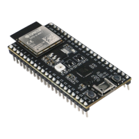
ESP32-S2-WROVER Module Module integrating the ESP32-S2 chip that provides Wi-Fi connectivity, data
processing power, and flexible data storage.
4.3”LCD FPC Connector (Reserved) Connect to a 4.3”LCD extension board using the FPC cable.
ESP Prog Connector (Reserved) Connection for Espressif’s download device (ESP-Prog) to flash
ESP32-S2 system.
JTAG Switch Switch to ON to enable connection between ESP32-S2 and FT2232; JTAG
debugging will then be possible using USB-UART/JTAG Port. See also JTAG
Debugging.
Breakout Header 2 Some GPIO pins of the ESP32-S2-WROVER module are broken out to this
header, see labels on the board.
USB-to-UART/JTAG Bridge FT2232 adapter board allowing for communication over USB port using
UART/JTAG protocols.
Camera Header Mount a camera extension board here (e.g., ESP-LyraP-CAM).
Extension Header Mount the extension boards having such connectors here.
Reset Button Press this button to restart the system
Boot Button Holding down Boot and then pressing Reset initiates Firmware Download
mode for downloading firmware through the serial port.
USB-UART/JTAG Port Communication interface (UART or JTAG) between a PC and the ESP32-S2
module.
USB Power Port Power supply for the board.
Battery Port Connect an external battery to the 2-pin battery connector.
Power On LED Turns on when the USB or an external power supply is connected to the board.
Power Switch Switch to ON to power the system.
RGB Jumper To have access to the RGB LED, place a jumper onto the pins.
RGB LED Programmable RGB LED and controlled by GPIO45. Before using it, you
need to put RGB Jumper ON.
Power Regulator Regulator converts 5 V to 3.3 V.
I2C FPC Connector (Reserved) Connect to other I2C extension boards using the FPC cable.
Breakout Header 1 Some GPIO pins of the ESP32-S2-WROVER module are broken out to this
header, see labels on the board.
Touch FPC Connector Connect the ESP-LyraP-TouchA extension board using the FPC cable.
Touch Switch In OFF position, GPIO1 to GPIO14 are used for connection to touch sensors;
switch to ON if you want to use them for other purposes.
3.2”LCD FPC connector Connect a 3.2”LCD extension board (e.g., ESP-LyraP-LCD32) using the FPC
cable.
Start Application Development Before powering up your ESP32-S2-Kaluga-1, please make sure that it is in good
condition with no obvious signs of damage.
Required Hardware
• ESP32-S2-Kaluga-1
• Two USB 2.0 cables (Standard-A to Micro-B)
– For power supply
– For UART/JTAG communication
• Computer running Windows, Linux, or macOS
• Any extension boards of your choice
Hardware Setup
Espressif Systems 24
Submit Document Feedback
Release v4.4