Chapter 1. Get Started
Description of Components
Key Component Description
Main Board Camera Header Mount onto main board’s Camera Header
Power ON LED Red LED is on if the power supply voltage is applied
Camera Module Connector Supports OV2640 and OV3660 camera modules; this extension board is sup-
plied with an OV2640 camera module
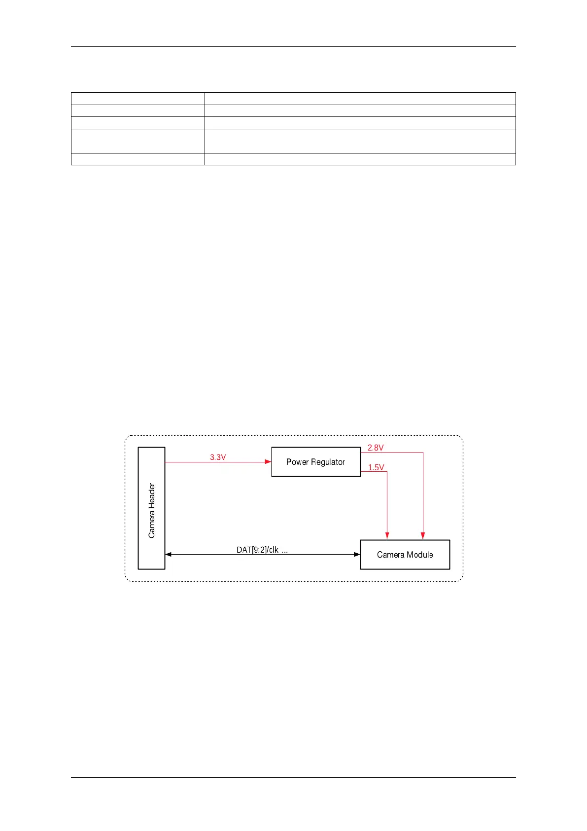
Power Regulators LDO Regulators converting 3.3 V to 2.8 V and 1.5 V
Start Application Development Before powering up your ESP-LyraP-CAM, please make sure that it is in good
condition with no obvious signs of damage.
Required Hardware
• Board with a female Camera Header (e.g., ESP32-S2-Kaluga-1)
• ESP-LyraP-CAM extension board
• Computer running Windows, Linux, or macOS
Hardware Setup Insert the ESP-LyraP-CAM extension board into your board’s female Camera Header.
Software Setup See Section Software Setup of the ESP32-S2-Kaluga-1 kit user guide.
Hardware Reference
Block Diagram A block diagram below shows the components of the ESP-LyraP-CAM and their interconnections.
Fig. 26: ESP-LyraP-CAM block diagram
Hardware Revision Details No previous versions available.
Related Documents
• ESP-LyraP-CAM Schematic (PDF)
• ESP-LyraP-CAM PCB Layout (PDF)
For other design documentation for the board, please contact us at sales@espressif.com.
Espressif Systems 36
Submit Document Feedback
Release v4.4