5700MSC-IP
IP Network Grand Master Clock & Video Master Clock System
Page - 4 Revision 0.2
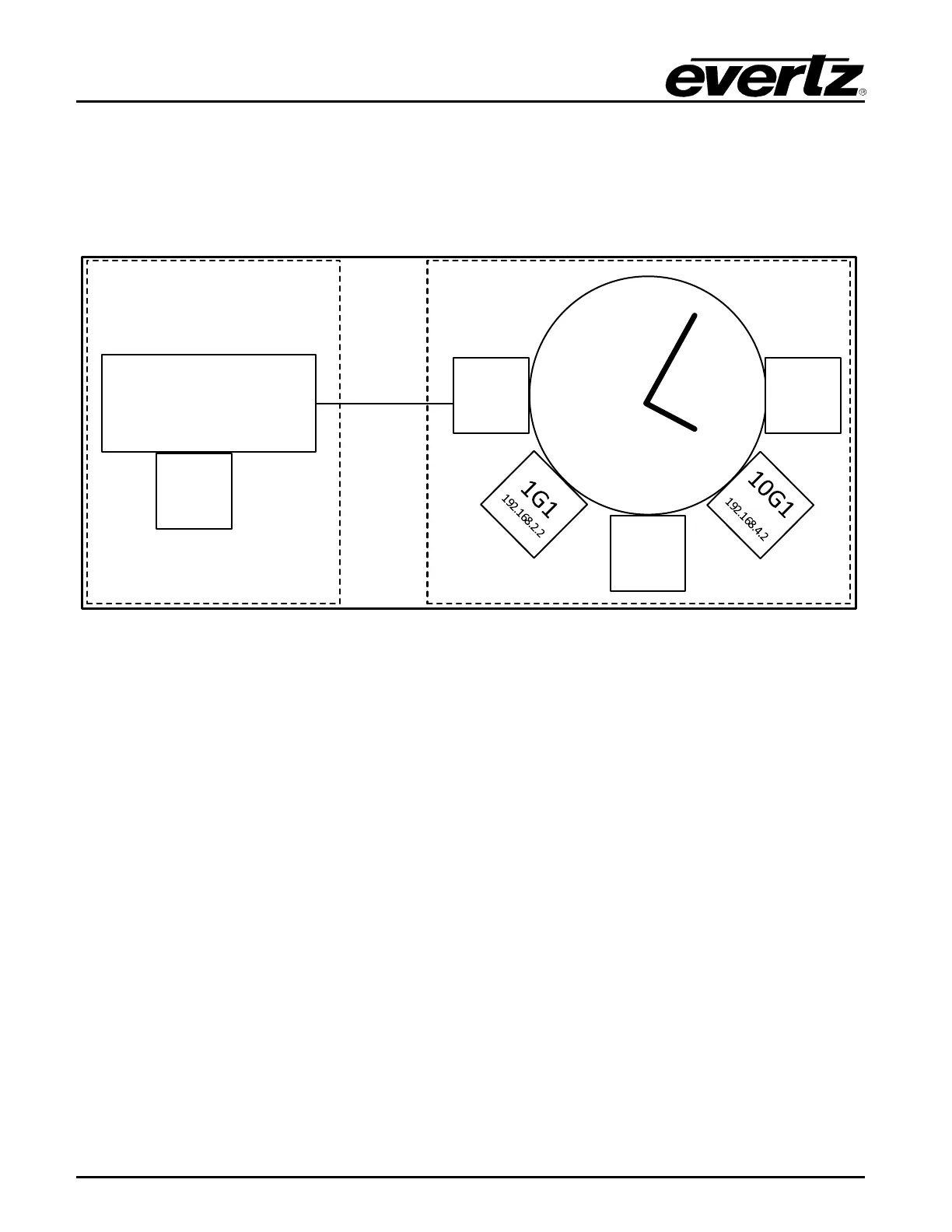
two 10Gb/s ports are located on the rear plate of the 7800MSC-10G, while the frame Ethernet port
shares the frame controller’s Ethernet port, and hence the same IP subnet. Each of the master clock
board interfaces must be configured with unique, valid IP addresses on separate IP subnetworks.
Please refer to Figure 1-2 as an example of how this is done.
7801FC-IRD
Frame Controller
192.168.
1.3
Frame
10/100
Ethernet
Port
10G
2
192.168
.5.2
Frame
Ethernet
(internal)
192.168.1.2
1G2
192.168.3.2
Internal
Conne ction
7800MSC-10
G
Board
Figure 1-2: Ethernet Port Configuration
Press the GENERAL button on the front panel to access the general setup menu. This menu can be
used to configure the two 1Gb/s Ethernet ports, the frame Ethernet port and the two 10Gb/s Ethernet
SFP ports on the 5700MSC-IP. The 1GigE 1, 1GigE 2, 10GigE 1 and 10GigE 2 ports are used to carry
mission-critical data, such as PTP, NTP and PCR. The frame Ethernet port is used for management
purposes (VistaLink Pro, syslog, firmware updates, etc.).
The current menu selection will be indicated by the > character. Rotate the control knob or press the
and buttons to select the IP Control menu item and press the SELECT button or depress the knob.
Assign an unused IP address and subnet mask to the the two 1Gb/s Ethernet ports, the frame
Ethernet port and the two 10Gb/s Ethernet SFP ports. The five ports must be on separate subnets in
order to function properly. When entering an IP address, the control knob can be used to set each
octet. Depress the control knob while turning to adjust in larger steps. The Ethernet link status and
current IP settings can be viewed by pressing the STATUS button and selecting the the either of the
two 1Gb/s Ethernet ports, the frame Ethernet port or either of the two 10Gb/s Ethernet SFP ports
status screens.
If SNMP monitoring or control of the unit is desired, the SNMP feature must first be enabled (it is
disabled by default). Select the GENERAL menu and press ESC to return to the root menu. Scroll
down to EngineeringMenu and press SELECT. A password is required to enable the engineering
menu items. Press SELECT on Password and use the and buttons or control knob to enter each
digit of the numeric password and then press SELECT. The default password is 5700. The SNMP
menu should now be accessible and SNMP can be enabled through SNMP Ctl. The trap addresses
must be assigned if SNMP traps are required to be sent to remote logging software such as