5700MSC-IP
IP Network Grand Master Clock & Video Master Clock System
Page - 24 Revision 0.2
3.2. GENLOCK
3.2.1. Frequency Locking
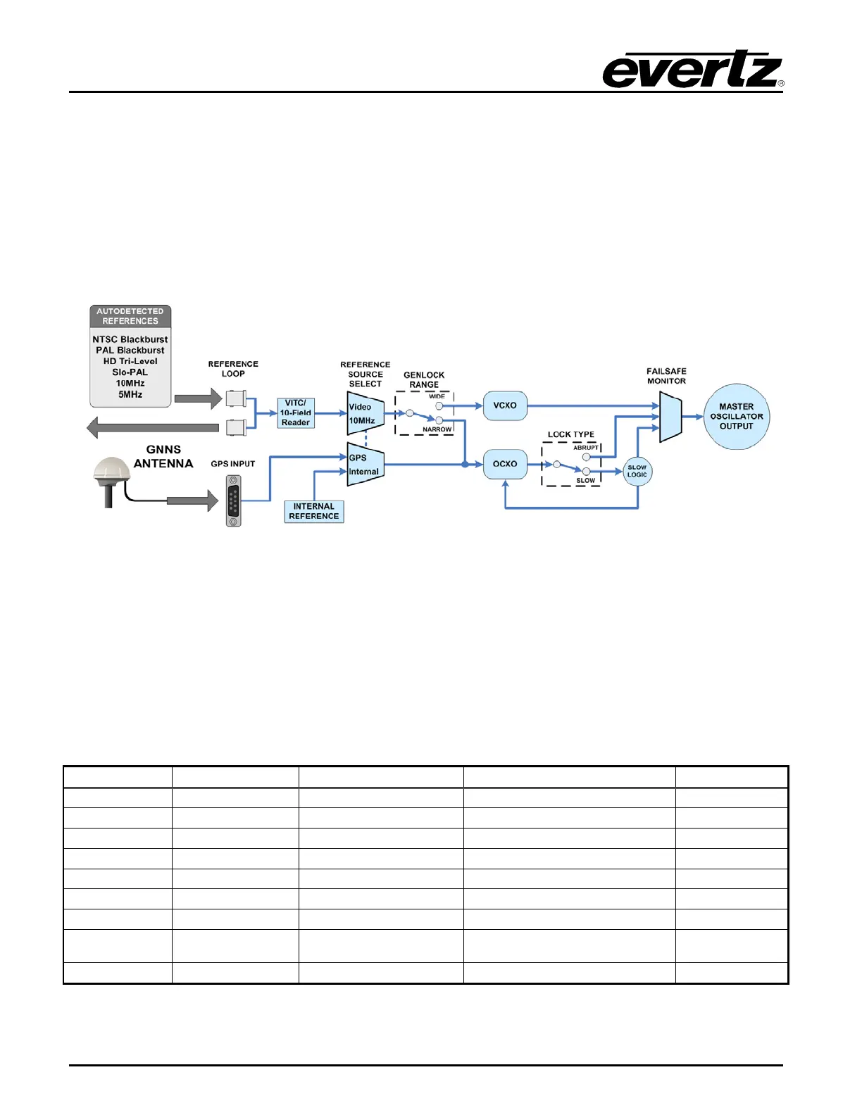
At the heart of the 5700MSC-IP is the master oscillator circuit. Refer to the block diagram in Figure 3-5
below. For maximum versatility and reliability, two separate oscillators are employed. In narrow mode,
an ovenized quartz oscillator (OCXO) is used for maximum stability. In wide mode, a voltage controlled
oscillator (VCXO) provides a wide lock range and fast lock times. For added reliability this dual
configuration allows the unused oscillator to act as a backup to the active oscillator. In the case of a
hardware fault the backup oscillator will take over.
Figure 3-5: Main Oscillator Circuit Block Diagram
The 5700MSC-IP can be configured to free-run on its internal reference, or it can lock its oscillator to
an available frequency reference. This locking operation uses a Phase Lock Loop (PLL) to
continuously adjust the oscillator to track the frequency and phase of the reference signal. In narrow
mode an additional feature is available whereby the adjustment rate of the oscillator is limited to
prevent sudden changes during a re-locking operation (see Slow mode in section 3.2.4). The
5700MSC-IP can lock to several different frequency reference types. The supported signal types are
shown in Table 3-2. Video and Continuous Wave (CW) signals are applied to the frame reference 1
BNC, frame reference 2 BNC or reference loop HD-BNCs and are auto-detected. A GNSS receiver
can also be connected to the unit and used as a frequency reference (see section 3.5). Each reference
type is explained in detail in the following sections.
GNSS 1pps edge
4004 PAL frames/
4800 NTSC frames
Figure 3-12
Narrow only
Table 3-2: Frequency Reference Types for the 5700MSC-IP