5700MSC-IP
IP Network Grand Master Clock & Video Master Clock System
Revision 0.2 Page - 71
The fifth line displays the status of the LTC/IRIG input. If LTC is present it will show
“
LTC ok IRIG n/a”. If IRIG is present it will show “LTC n/a IRIG ok”
The sixth line shows the status of the General Purpose Inputs. These GPI inputs
are activated by connection to ground. The status will be “
GPI1 LO” or “GPI2 LO”
when either GPI has been activated.
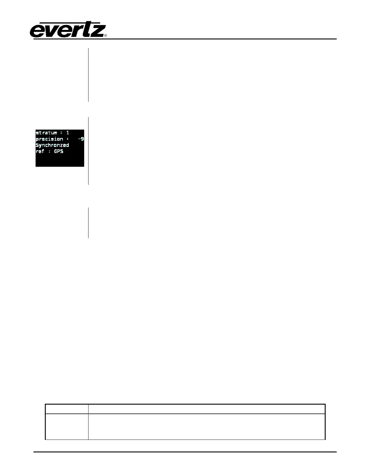
The NTP status screen displays information about the NTP server. It shows
stratum, precision, lock status, and reference.
It will also show if there are issues with the NTP. The HELP button will offer
suggestions if there is a configuration issue. If the NTP server is Not Synchronized
the lock indicator alarm bit (LI_ALARM) will be set in outgoing packets. This may
cause clients to refuse to synchronize to the NTP server.
Press HELP for more information on the current status.
Image will be
added in upcoming
release
The Options Firmware status screen displays information about the installed
options in the 5700MSC-IP as well as the current firmware version.
The last line shows the current firmware version and build number that is installed
in the 5700MSC-IP in the format of: Version X.X Build XX.
5.1.3. Panel Lock Function
Pressing the PANEL LOCK button will lock the front panel. The PANEL LOCK button will illuminate
indicating that the front panel keys are disabled. This is used to prevent accidental changes to the unit
once it has been configured. While the front panel is locked, the STATUS screens will still be
accessible. It will still be possible to press the STATUS button and view the various status screens but
it will not be possible to enter any other menu or change menu items. To unlock the panel, press the
PANEL LOCK button while holding the SELECT button. The front panel will return to normal operation
and the PANEL LOCK button LED will turn off. Note that pressing HELP and PANEL LOCK at the
same time will also turn off the panel lock.
5.1.4. Front Panel LCD Displays
There are two full color LCD displays on the front panel. The left LCD indicates the current position in
the menu structure as well as system health status. The right LCD is used to display the menu system
and status screens.
The left LCD display shows the current position in the menu tree. In the bottom-left corner the system
status is shown. A critical fault will appear in red blinking text. The possible system status messages
are summarized in Table 5-1 in order of severity:
Hw fail
Appears blinking red in the bottom-
left corner. Indicates that an internal
hardware problem has been detected. It is advisable not to remove power from
the unit and to contact the factory immediately.