5700MSC-IP
IP Network Grand Master Clock & Video Master Clock System
Revision 0.2 Page - 57
4. INSTALLATION
4.1. REAR PANEL
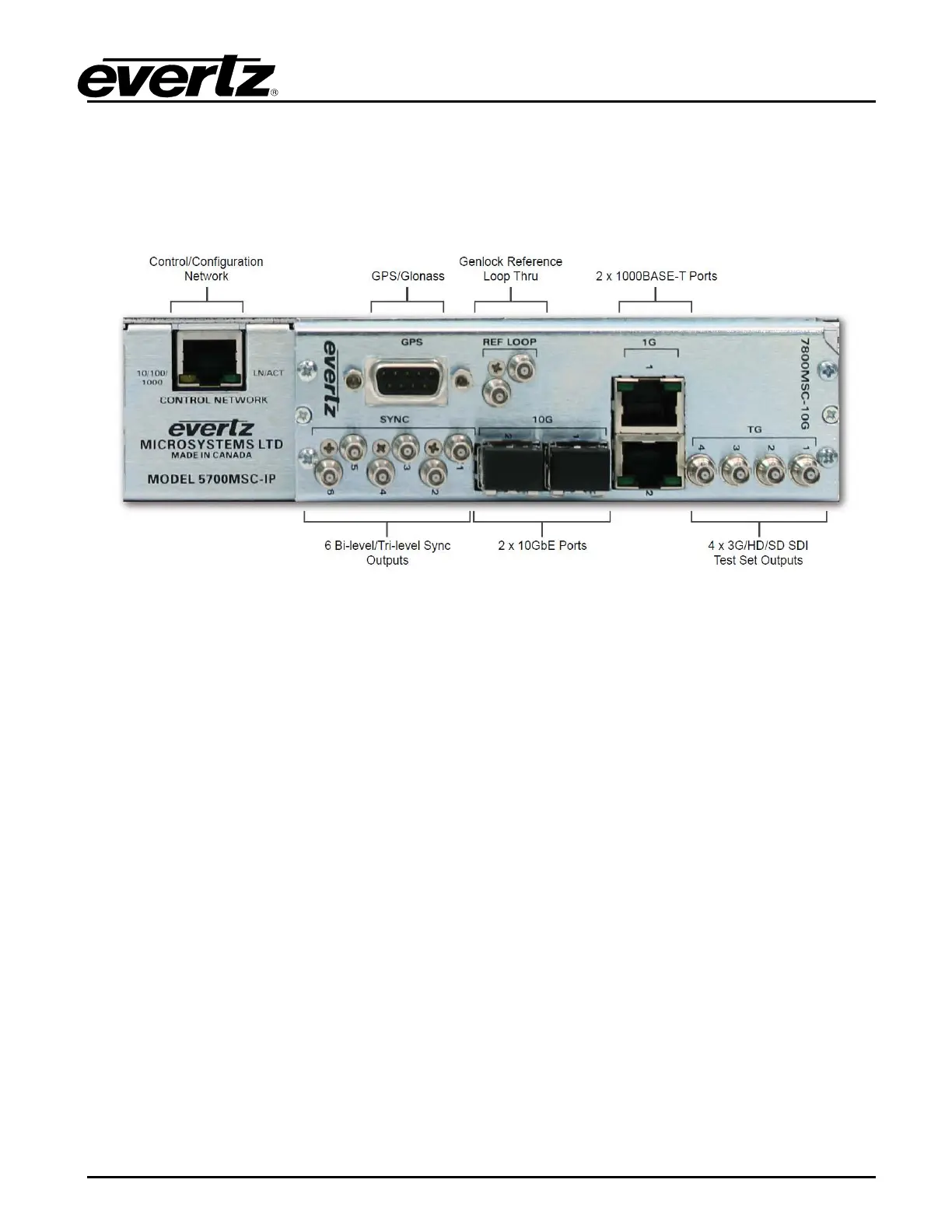
Figure 4-1 provides an illustration of the 5700MSC-IP rear panel.
Figure 4-1: 5700MSC-IP Rear Panel
4.1.1. Reference Loop Connections
The two REF IN LOOP HD-BNC connectors provide a reference loop input for black burst, tri-level,
and 5MHz/10MHz signals. The HD-BNCs are isolated from chassis ground. The frequency reference
source must be set to Video in order to genlock to black burst or tri-level video signals. It must be set
to 10MHz in order to lock to 5MHz or 10MHz reference signals. The loop is high impedance and will
need to be properly terminated with 75 ohms using an external termination.
4.1.2. Sync Outputs
SYNC 1 to 6 - These HD-BNC connectors provide six independent programmable sync outputs that are
configured by the SYNC 1 to SYNC 6 group of sub-menus in the OUTPUT setup menu. The 5700MSC-
IP+AUX provides two additional HD-BNC connectors: SYNC 7 and SYNC 8. Each output can be
configured for any format of sync output from black burst, to tri-level, to 5MHz/10MHz, to wordclock,
and more.
10 MHz OUT (SYNC 7) - This HD-BNC connector provides a 10MHz frequency reference but can also
be programmed as another sync output. It is recommended that this output be configured as a 10MHz
output when used in conjunction with an automatic changeover unit to simplify wiring. It is configured
using the 10 MHz sub-menu in the OUTPUT setup menu.
WORDCLOCK (SYNC 8) - This HD-BNC connector provides a 48kHz wordclock signal but can also be
programmed as another sync output. It is recommended that this output be configured as a wordclock
output when used in conjunction with an automatic changeover unit to simplify wiring. It is configured
using the Wordclock sub-menu in the OUTPUT setup menu.