5700MSC-IP
IP Network Grand Master Clock & Video Master Clock System
Page - 60 Revision 0.2
+ 12 Volts DC out to supply GNSS receiver
Table 4-3: GNSS Serial Port Pin Definitions
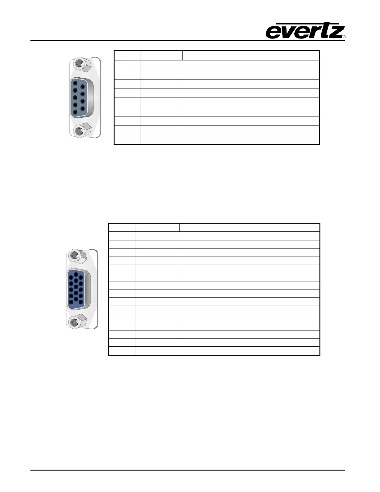
4.1.6. AUX Connections (available with 5700MSC-IP+AUX option)
4.1.7. GPIO, LTC Input, Secondary LTC Outputs
These connections are available with the 5700MSC-IP+AUX option. A 15-pin female ‘D’ connector
provides two general purpose inputs, two general purpose outputs, secondary LTC1 and LTC2
outputs, and an LTC input. A 15-pin male-male cable is used for this purpose. The pinout of the GPIO
connector is shown in Table 4-4.
Secondary Linear Time Code Output 1 -
Secondary Linear Time Code Output 2 -
Secondary Linear Time Code Output 1 +
Secondary Linear Time Code Output 2 +
Table 4-4: GPIO Pin Definitions
4.1.8. Unbalanced Audio Connections AES 1, 2 and 3 (available with 5700MSC-IP+AUX option)
These three connectors provide unbalanced 48kHz AES audio compatible with the AES3-1992 and
SMPTE 276M standards. Balanced versions of these signals are available on the AUDIO 16-pin
terminal strip. The AES Audio sub-menu in the OUTPUT root menu is used to configure the AES audio
outputs.