5700MSC-IP
IP Network Grand Master Clock & Video Master Clock System
Page - 58 Revision 0.2
4.1.3. Ethernet Connections
The 5700MSC-IP is equipped with 5 interfaces, of which one is furnished through the 1G copper frame
controller port (called the FP), two 1G copper ports on the rear plate, and two 10G SFP ports on the
rear plate. All ports can do PTP, PCR, NTP, FTP and SNMP. Additionally, the two 10G SFP ports also
provide three IP Test Generator signals. The 1G ports can be used with 10Base-T (10 Mbps),
100Base-TX (100 Mbps) or 1000Base-TX (1000Mbps) twisted pair Ethernet cabling systems. When
connecting for 10Base-T systems, category 3, 4, or 5 UTP cable as well as EIA/TIA – 568 100Ω STP
cable may be used. When connecting for 100Base-TX systems, category 5 or better UTP cable is
required. The cable must be “straight through” with an 8-pin modular connector at each end. Make the
network connection by plugging one end of the cable into the CONTROL receptacle of the 5700MSC-
IP and the other end into an Ethernet hub or switch. The CONTROL port hosts an NTP server (with
periodic broadcasts) and an SNMP server for remote monitoring and control.
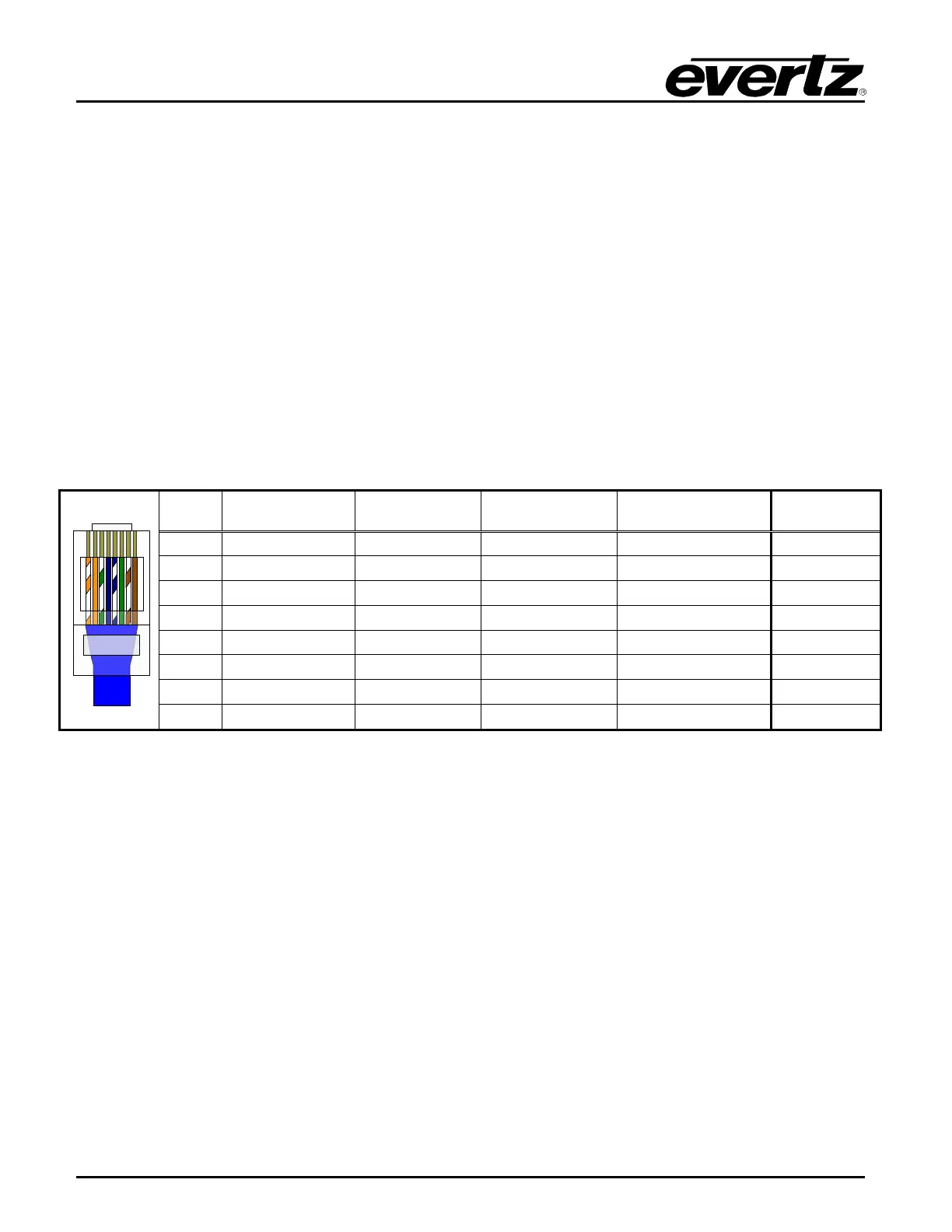
The straight-through Ethernet cable can be purchased or can be constructed using the pinout
information in Table 4-1. A color code wiring chart is provided in Table 4-1 for the current Ethernet
standards (AT&T 258A or EIA/TIA 258B color coding shown). Also refer to the notes following the
table for additional wiring guide information.
Pin # Signal EIA/TIA 568A
AT&T 258A or
EIA/TIA 568B
1 Transmit + White/Green White/Orange X
8 Bi-Directional – Brown Brown Not used (required)
Table 4-1: Standard 8-pin Modular Connector Wiring Color Codes
Note the following cabling information for this wiring guide:
• Only two pairs of wires are used in the 8-pin modular connector to carry Ethernet signals for
10BaseT and 100BaseTX. 1000BaseT uses all four pairs.
• Even though pins 4, 5, 7 and 8 are not used for 10BaseT and 100BaseTX, it is mandatory that
they be present in the cable.
• 10BaseT and 100BaseTX use the same pins; the same crossover cable will work with both.
• Pairs may be solid colors and may not have a stripe.
• Category 5 cable must use Category 5 rated connectors.
The maximum cable run between the 5700MSC-IP and the supporting switch is 328 ft (100 m). The
maximum combined cable run between any two end points (i.e. 5700MSC-IP and PC/laptop via
Ethernet switch) is 656 feet (200 m) when using copper cable.
Devices on the Ethernet network continually monitor the receive data path for activity as a means of
checking that the link is working correctly. When the network is idle, the devices also send a link test
signal to one another to verify link integrity. The 5700MSC-IP rear panel is fitted with two LEDs to
monitor the Ethernet connection.