5700MSC-IP
IP Network Grand Master Clock & Video Master Clock System
Page - 70 Revision 0.2
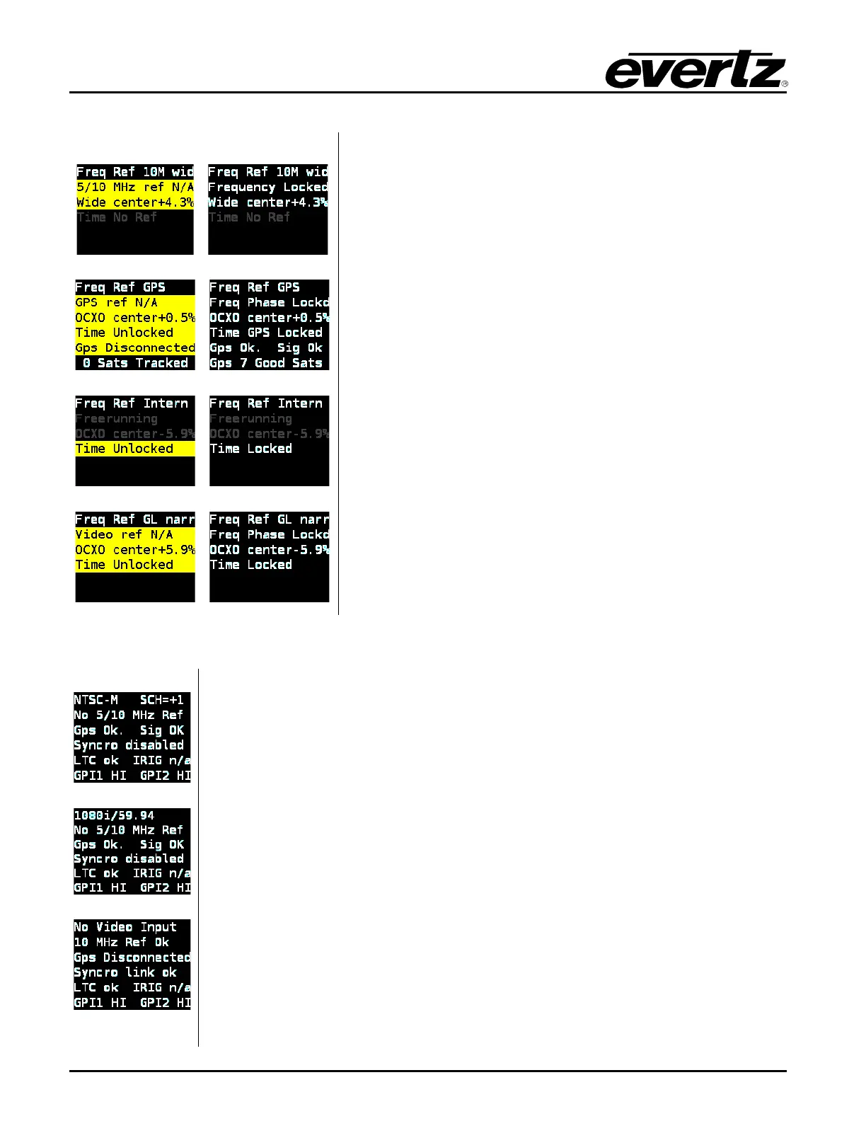
[#1] 10MHz frequency ref, no time ref
[#2] GPS frequency ref, GPS time ref
[#3] No frequency ref, Modem time ref
[#4] Video frequency ref, VITC time ref
The Lock Status screen displays the current status of the
selected frequency and time references for the 5700MSC-IP.
The first line indicates which frequency reference has been
selected, and if the unit is using the narrow or wide oscillator.
The second line shows the
overall lock status of the
5700MSC-IP to the selected frequency reference. This line will
display “
Lock progrs x%” while locking to show the current
progress in locking the oscillator to the reference. This line
also indicates if the 5700MSC-IP
has locked to frequency
only, or has both frequency and phase locked to the
reference.
The third line indicates the current tuning position of the
selected oscillator when locked to the reference.
The fourth line displays the current lock status of the system
clock to the time reference.
The fifth and sixth li
nes display the status of the GNSS
receiver when GNS
S has been selected as a frequency or
time reference. The fifth line displays the current GNSS lock
state, and the sixth line displays how many healthy satellite
signals the GNSS antenna is receiving.
NTSC ref with GPS
1080i ref with GPS
10MHz ref with Syncro
The Inputs status screen displays the status of the reference inputs, syncro link,
and General Purpose Inputs.
The first line displays the name of the detected video reference that is present on
the reference loop input.
For NTSC-M and PAL-
B black burst references, an approximate Subcarrier to
Horizontal (SCH) measurement of the input will be shown. If the S
greater than 35º, this line will alternate between “(SCH>35)” and “H-lock
indicate that the 5700MSC-IP has fallen back to locking to horizontal sync only. If
the burst phase cannot be measured reliably, it will display “
unlockable”.
The se
cond line displays the detection of a 10MHz or 5MHz continuous wave
(CW) frequency on the reference loop input.
The third line displays the current status of the GPS receiver. This is the same
status that is displayed on line 5 of the Lock Status screen.
The fourth line shows the current status of the syncro link (if enabled)
available when two 5700MSC-IP
units are connected through an automatic
changeover unit.