EVS Broadcast Equipment SA
Issue 2.0.7.2 September 2021
38 Processing Module Installation and Cabling
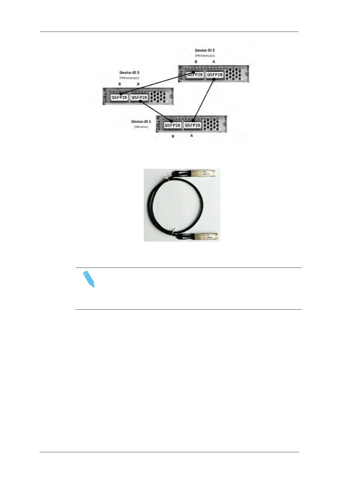
Figure: Direct-3 cabling scheme
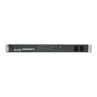
Figure: QSFP28 Twinax cable
Note
The Device-ID identifies the role of a processing module within
a cluster (PM-Main or PM-Extension). For details on how to set
Device-IDs, refer to section 11.2.3.
Using a Network Switch (Topology: Switch- 100G)
For more flexible solutions, multiple Processing Modules can be
connected through a 100 GigE network switch.
The Switch-100G topology allows to build a production with multiple
Processing Modules connected to a switch. The QSFP28 port A of each
Processing Module must be connected to 100 GigE QSFP28 ports of a
Deep Buffer network switch such as the ARISTA 7280QR-C36