Maintenance
Periodic Maintenance
Lubrication
Greasing the Machine
Grease with No . 2 lithium or molybden um g rease .
1. Diseng ag e the blade-control switc h (PTO) and
mo v e the motion-control lev ers outw ard to the
P ark position.
2. Shut off the mac hine , remo v e the k ey , and w ait
for all mo ving par ts to stop before lea ving the
operating position.
3. Clean the g rease ttings with a rag .
Note: Mak e sure to scrape any paint off the front
of the tting(s).
4. Connect a g rease gun to the tting .
5. Pump g rease into the ttings until g rease begins
to ooze out of the bearings .
6. Wipe up any ex cess g rease .
Greasing the Front Caster Pivots
Service Interval : Y early
Gr ease type: Lithium or molybden um g rease
1. R emo v e the dust cap and
adjust the caster pi v ots; refer to
Adjusting the Caster -Pi v ot Bearing ( pag e 40 ) .
Note: K ee p the dust cap off until y ou ha v e
nished g reasing the caster pi v ots .
2. R emo v e the hex plug .
3. T hread a g rease tting (1/4 inc h–28 taper thread)
into the hole .
4. Pump g rease into the tting until it oozes out
around the top bearing .
5. R emo v e the g rease tting from the hole .
6. Install the hex plug and dust cap .
Greasing the Caster-Wheel Hubs
Service Interval : Y early
Gr ease type: Lithium or molybden um g rease
1. P ark the mac hine on a lev el surface , diseng ag e
the PTO , and mo v e the motion-control lev ers
outw ard to the P ark position.
2. Shut off the mac hine , remo v e the k ey , and w ait
for all mo ving par ts to stop before lea ving the
operating position.
3. R emo v e the caster wheel from the caster forks .
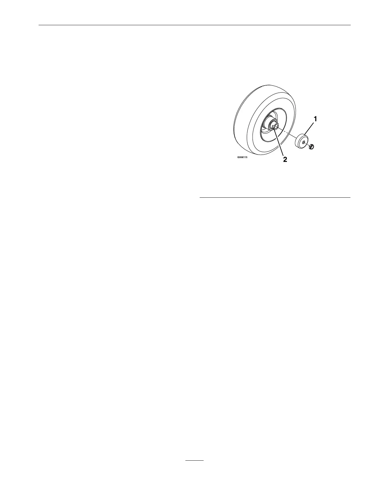
4. R emo v e the seal guards from the wheel hub .
g006115
Figure 45
1. Seal guard 2. Spacer nut with wrench
ats
5. R emo v e 1 spacer n ut from the axle assembly in
the caster wheel.
Note: T hread-loc king adhesi v e has been applied
to loc k the spacer n uts to the axle .
6. R emo v e the axle with the other spacer n ut still
assembled to it from the wheel assembly .
7. Pr y out the seals , inspect bearings for w ear or
damag e , and re place them if necessar y .
8. P ac k the bearings with a g eneral-pur pose g rease .
9. Inser t 1 bearing and 1 new seal into the wheel.
Note: Y ou m ust re place the seals .
10. If both spacer n uts in the axle assembly ha v e been
remo v ed (or brok en loose), apply thread-loc king
adhesi v e to 1 spacer n ut, threading it onto the axle
with the wrenc h ats facing outw ard.
Note: Do not thread the spacer n ut all of the
w a y onto the end of the axle . Lea v e appro ximately
3 mm (1/8 inc h) from the outer surface of the
spacer n ut to the end of the axle inside the n ut.
11. Inser t the assembled n ut and axle into the wheel
on the side of the wheel with the new seal and
bearing .
12. With the open end of the wheel facing up , ll
the area inside the wheel around the axle full of
g eneral-pur pose g rease .
13. Inser t the second bearing and the new seal into
the wheel.
37
 Loading...