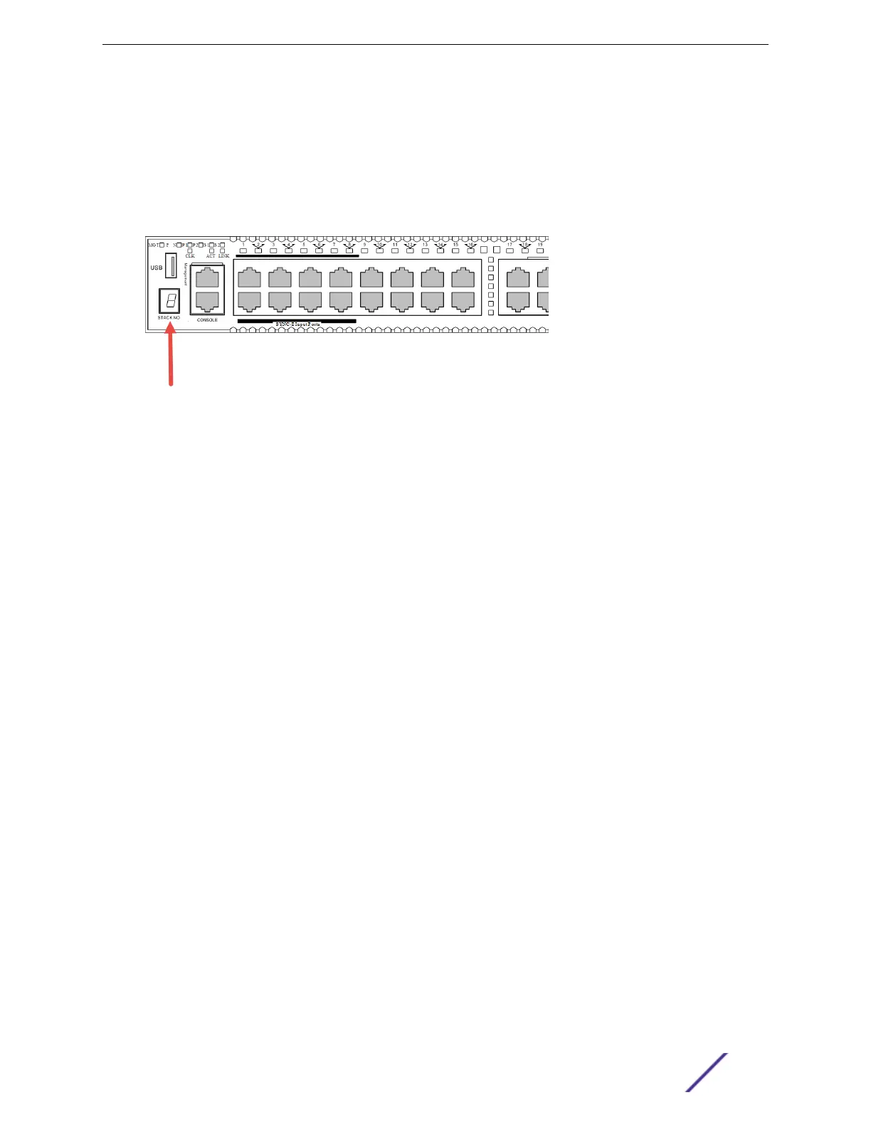
Some stackable switches have a seven-segment LED, called the stack number indicator on the front
panel. (See Figure 115.) When a stack is operating, the indicator displays the switch's slot number. This
LED does not light on switches that are not currently operating as part of a stack.
The top half of the number blinks if the switch is the master, and the bottom half blinks if it is the
backup. If the LED is steadily lit, the switch is a standby. If the LED is o the switch is not configured as a
member of a stack.
Figure 115: Position of the Stack Number Indicator (X460-G2 Switch Shown)
In addition to the Stack Number Indicator, each stacking port has an LED. The LED is steady green if the
link is OK, blinking green if trac is present, and o if no signal is present.
A quick way to verify that the cable connections match the software configuration is to check the stack
number indicator on each switch. If the slot numbers do not line up in the order you arranged the
switches, this might indicate that the stacking cable setup diers from what you intended when you
configured the software. In this case, reconnect the cables in the correct order and perform the
software configuration again.
Master/Backup Switch Redundancy
When your stack is operational, one switch is the master switch, responsible for running network
protocols and managing the stack.
To provide recovery in case of a break in the stack connections, you can configure redundancy by
designating a backup switch to take over as master if the master switch fails. When you perform the
initial software configuration of the stack, the “easy setup” configuration option automatically
configures redundancy, with slot 1 as the master and slot 2 as the backup. You can also configure
additional switches as “master-capable,” meaning they can become a stack master in case the initial
backup switch fails.
When assigning the master and backup roles in mixed stacks, consider the feature scalability and the
speed of each switch model. The easy setup configuration process selects master and backup switches,
based on capability and speed, in the following order:
1 Summit X670-G2
2 Summit X460-G2
3 Summit X770
4 Summit X450-G2
5 ExtremeSwitching X440-G2 and X620
For example, in a stack that combines Summit X460-G2 or X670-G2 switches with other switch models,
an X460-G2 or X670-G2 switch might provide more memory and more features than other switches in
Building Stacks
ExtremeSwitching and Summit Switches: Hardware Installation Guide 138
 Loading...


