1 Completely loosen the captive retaining screws on the fan module.
On most switch models, the fan module has two retaining screws at the bottom corners of the
module, as shown in Figure 244.
On some switch models, the fan module has a single retaining screw at the top right corner of the
module.
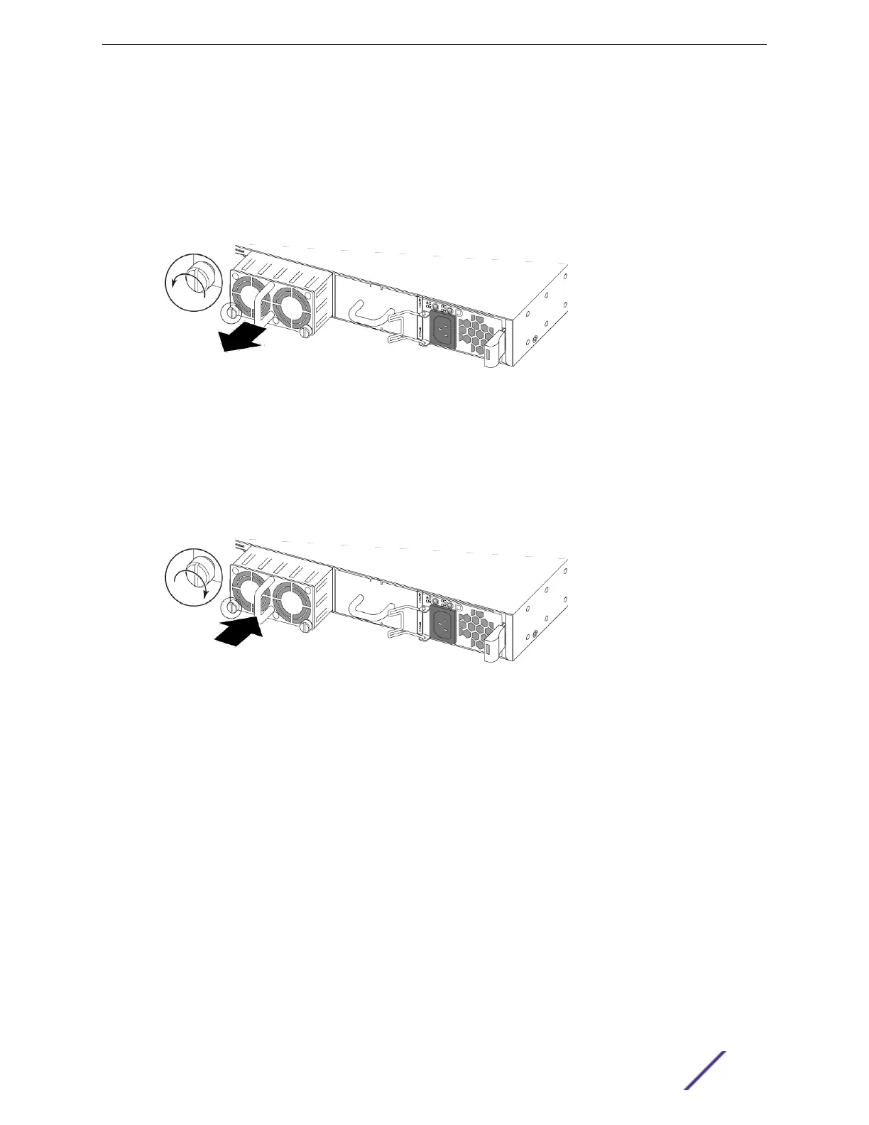
2 Slide the fan module out of the switch and set it aside.
Figure 244: Removing a Fan Module
3 Verify that the airflow direction on the replacement fan module matches that of the installed fan
modules.
Fans with front-to-back airflow are labeled Air Out.
Fans with back-to-front airflow are labeled Air In.
4 Carefully slide the replacement fan module into the switch.
Figure 245: Installing a Fan Module
5 Align and fully tighten the captive retaining screws.
Replacing Fan Modules
ExtremeSwitching and Summit Switches: Hardware Installation Guide 307
 Loading...


