RPS-150XT Connector
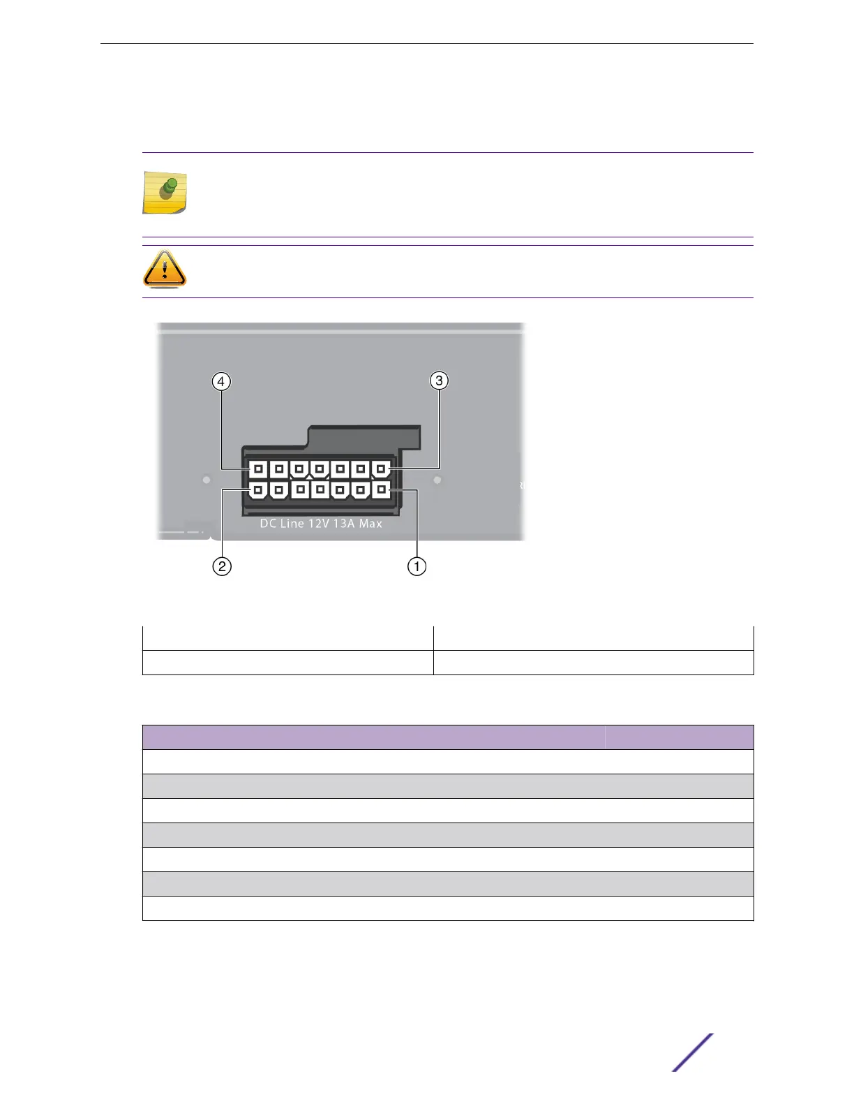
See Figure 253 and Table 285 on page 385 for pin locations and function.
Note
The following information is for troubleshooting purposes only. For proper operation, use only
the RPS cable supplied with the RPS-150XT. This cable is specially designed for this
application and meets all necessary regulatory and safety standards.
Caution
The use of non-approved cables will void your warranty.
Figure 253: RPS-150XT Connector Pin Locations
1 = Pin 1
3 = Pin 8
2 = Pin 7 4 = Pin 14
Table 285: RPS-150XT Connector Pin Functions
Pin Function Pin Function
1 Ground 8 Spare pin
2 Spare pin 9 Spare pin
3 12 V power 10 Power present
4 12 V power 11 Start 1
5 12 V power 12 Start 2
6 12 V power 13 Power good
7 Ground 14 Ground
Technical Specifications
ExtremeSwitching and Summit Switches: Hardware Installation Guide 385
 Loading...


